GE Multilin G60 Generator Protection System 5-287
5 SETTINGS 5.7 CONTROL ELEMENTS
5
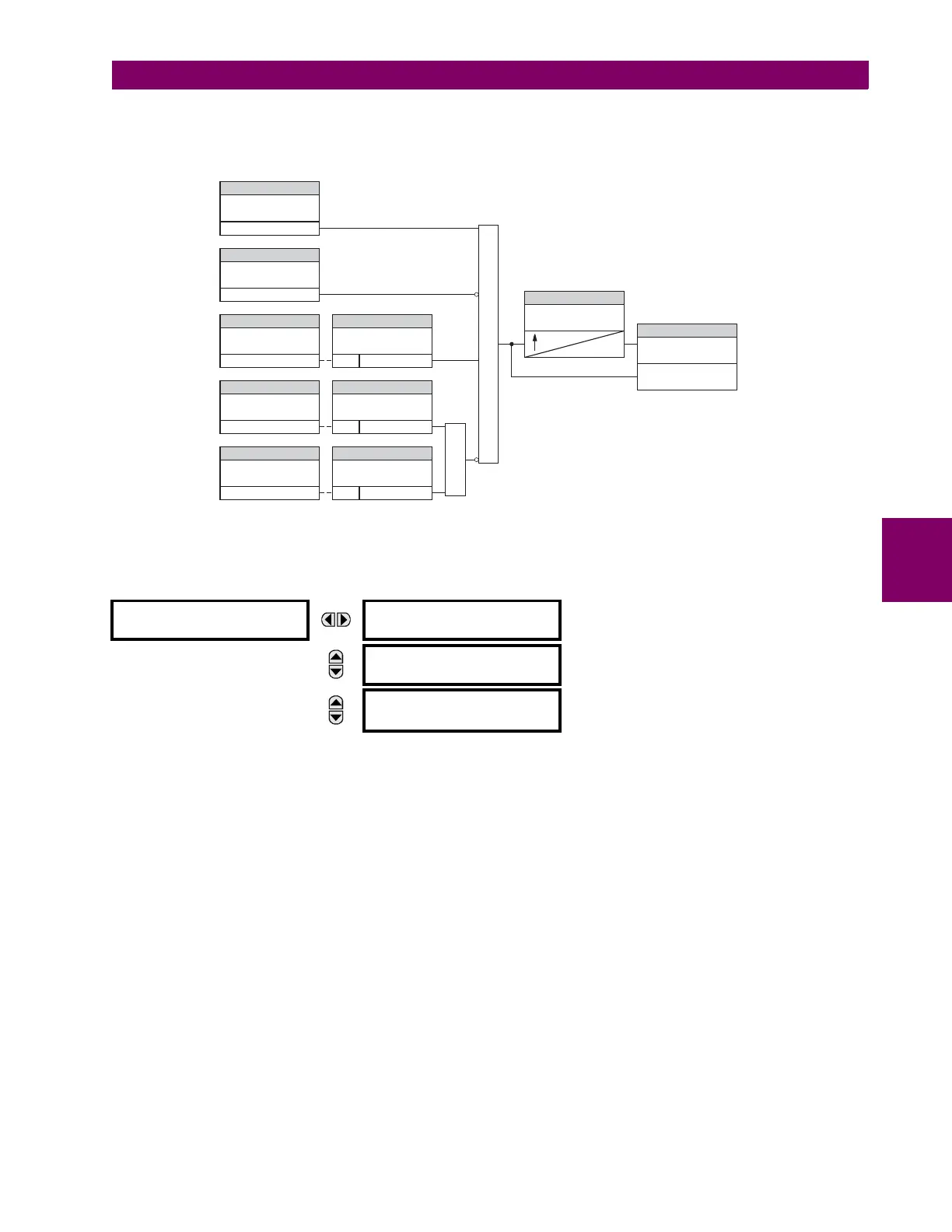
• CT FAIL 3V0 INPUT PICKUP: This setting specifies the pickup value for the 3V_0 source.
• CT FAIL PICKUP DELAY: This setting specifies the pickup delay of the CT failure element.
Figure 5–154: CT FAILURE DETECTOR SCHEME LOGIC
d) VT FUSE FAILURE
PATH: SETTINGS CONTROL ELEMENTS MONITORING ELEMENTS VT FUSE FAILURE 1(4)
Every signal source includes a fuse failure scheme.
The VT fuse failure detector can be used to raise an alarm and/or block elements that may operate incorrectly for a full or
partial loss of AC potential caused by one or more blown fuses. Some elements that might be blocked (via the
BLOCK input)
are distance, voltage restrained overcurrent, and directional current.
There are two classes of fuse failure that occur:
• Class A: loss of one or two phases.
• Class B: loss of all three phases.
Different means of detection are required for each class. An indication of class A failures is a significant level of negative-
sequence voltage, whereas an indication of class B failures is when positive sequence current is present and there is an
insignificant amount of positive sequence voltage. Also rapid decrease in the phase voltages magnitude from a healthy
voltage level without disturbance in current can indicate a VT fuse fail conditions. These noted indications of fuse failure
can also be present when faults are present on the system, so a means of detecting faults and inhibiting fuse failure decla-
rations during these events is provided.
Once the fuse failure condition is declared, it is sealed-in until the cause that generated it disappears.
An additional condition is introduced to inhibit a fuse failure declaration when the monitored circuit is de-energized; positive-
sequence voltage and current are both below threshold levels.
The
VT FUSE FAILURE 1 FUNCTION setting enables and disables the fuse failure feature for Source 1 VT Fuse Fail.
VT FUSE FAILURE 1
VT FUSE FAILURE 1
FUNCTION: Disabled
Range: Disabled, Enabled
MESSAGE
NEUTRAL WIRE OPEN 1
DETECTION: Disabled
Range: Disabled, Enabled
MESSAGE
NEUTRAL WIRE OPEN 1
3 HARM PKP: 0.100
0.000 to 3.000 pu in steps of 0.001
CT FAIL FUNCTION:
CT FAIL BLOCK:
CT FAIL 3IO INPUT1: CT FAIL 3IO INPUT1 PKP:
CT FAIL 3VO INPUT: CT FAIL 3VO INPUT:
CT FAIL 3IO INPUT2: CT FAIL 3IO INPUT2 PKP:
CT FAIL PICKUP DELAY:
AND
OR
SETTING
Enabled=1
SETTING
SETTINGSETTING
SETTINGSETTING
SETTINGSETTING
SETTING
Off=0
SRC1 RUN 3IO > PICKUP
3IO > PICKUP
3VO > PICKUPSRC1 RUN
SRC2 RUN
FLEXLOGIC OPERANDS
CT FAIL OP
CT FAIL PKP
827048A7.CDR
0