5-318 G60 Generator Protection System GE Multilin
5.9 TRANSDUCER INPUTS AND OUTPUTS 5 SETTINGS
5
where: x is a driving signal specified by the SOURCE setting
I
min
and I
max
are defined by the RANGE setting
k is a scaling constant calculated as:
(EQ 5.54)
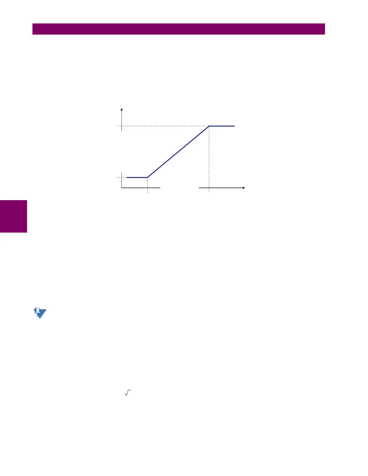
The feature is intentionally inhibited if the MAX VAL and MIN VAL settings are entered incorrectly, e.g. when MAX VAL – MIN
VAL < 0.1 pu. The resulting characteristic is illustrated in the following figure.
Figure 5–168: DCMA OUTPUT CHARACTERISTIC
The DCmA output settings are described below.
• DCMA OUTPUT H1 SOURCE: This setting specifies an internal analog value to drive the analog output. Actual values
(FlexAnalog parameters) such as power, current amplitude, voltage amplitude, power factor, etc. can be configured as
sources driving DCmA outputs. Refer to Appendix A for a complete list of FlexAnalog parameters.
• DCMA OUTPUT H1 RANGE: This setting allows selection of the output range. Each DCmA channel may be set inde-
pendently to work with different ranges. The three most commonly used output ranges are available.
• DCMA OUTPUT H1 MIN VAL: This setting allows setting the minimum limit for the signal that drives the output. This
setting is used to control the mapping between an internal analog value and the output current. The setting is entered
in per-unit values. The base units are defined in the same manner as the FlexElement base units.
• DCMA OUTPUT H1 MAX VAL: This setting allows setting the maximum limit for the signal that drives the output. This
setting is used to control the mapping between an internal analog value and the output current. The setting is entered
in per-unit values. The base units are defined in the same manner as the FlexElement base units.
The
DCMA OUTPUT H1 MIN VAL and DCMA OUTPUT H1 MAX VAL settings are ignored for power factor base units (i.e. if
the
DCMA OUTPUT H1 SOURCE is set to FlexAnalog value based on power factor measurement).
Three application examples are described below.
EXAMPLE: POWER MONITORING
A three phase active power on a 13.8 kV system measured via UR-series relay source 1 is to be monitored by the dcmA H1
output of the range of –1 to 1 mA. The following settings are applied on the relay: CT ratio = 1200:5, VT secondary 115, VT
connection is delta, and VT ratio = 120. The nominal current is 800 A primary and the nominal power factor is 0.90. The
power is to be monitored in both importing and exporting directions and allow for 20% overload compared to the nominal.
The nominal three-phase power is:
(EQ 5.55)
The three-phase power with 20% overload margin is:
(EQ 5.56)
k
I
max
I
min
–
MAX VAL MIN VAL–
-------------------------------------------------
=
842739A1.CDR
DRIVING SIGNAL
OUTPUT CURRENT
MIN VAL
I
min
I
max
MAX VAL
P 3 13.8 kV 0.8 kA× 0.9×× 17.21 MW==
P
max
1.2 17.21 MW× 20.65 MW==