GE Multilin G60 Generator Protection System 6-19
6 ACTUAL VALUES 6.3 METERING
6
f) POWER METERING
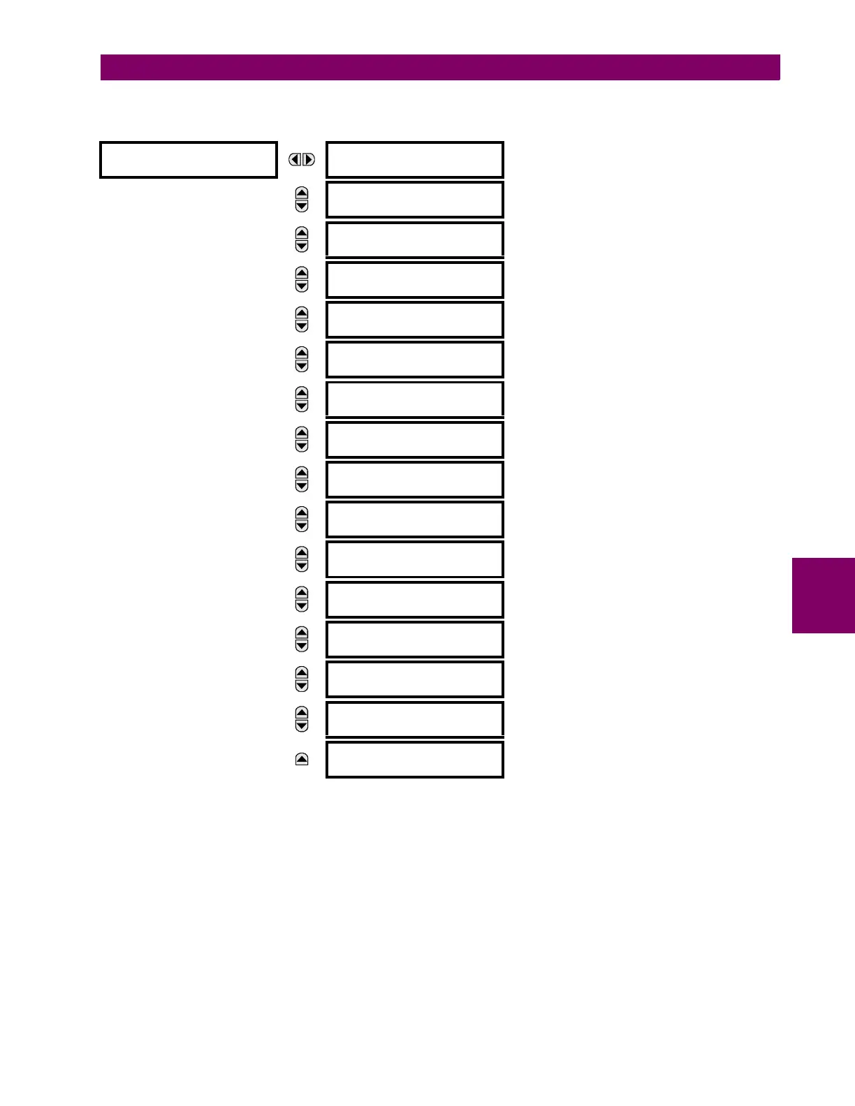
PATH: ACTUAL VALUES METERING SOURCE SRC 1 POWER
The metered values for real, reactive, and apparent power, as well as power factor, are displayed in this menu. The "SRC
1" text is replaced by whatever name was programmed by the user for the associated source (see
SETTINGS SYSTEM
SETUP
SIGNAL SOURCES).
When VTs are configured in wye, the G60 calculates power in each phase and three-phase power is measured as
S = V
A
x Î
A
+ V
B
x Î
B
+ V
C
x Î
C
(EQ 6.1)
When VTs are configured in delta, the G60 does not calculate power in each phase and three-phase power is measured as
S = V
AB
x Î
A
+ V
CB
x Î
C
(EQ 6.2)
where
S is the apparent power
V
A
, V
B
, V
C
, I
A
, I
B
, I
C
are phase voltage and phase current phasors
POWER
SRC 1
SRC 1 REAL POWER
3φ: 0.000 W
MESSAGE
SRC 1 REAL POWER
φa: 0.000 W
MESSAGE
SRC 1 REAL POWER
φb: 0.000 W
MESSAGE
SRC 1 REAL POWER
φc: 0.000 W
MESSAGE
SRC 1 REACTIVE PWR
3φ: 0.000 var
MESSAGE
SRC 1 REACTIVE PWR
φa: 0.000 var
MESSAGE
SRC 1 REACTIVE PWR
φb: 0.000 var
MESSAGE
SRC 1 REACTIVE PWR
φc: 0.000 var
MESSAGE
SRC 1 APPARENT PWR
3φ: 0.000 VA
MESSAGE
SRC 1 APPARENT PWR
φa: 0.000 VA
MESSAGE
SRC 1 APPARENT PWR
φb: 0.000 VA
MESSAGE
SRC 1 APPARENT PWR
φc: 0.000 VA
MESSAGE
SRC 1 POWER FACTOR
3φ: 1.000
MESSAGE
SRC 1 POWER FACTOR
φa: 1.000
MESSAGE
SRC 1 POWER FACTOR
φb: 1.000
MESSAGE
SRC 1 POWER FACTOR
φc: 1.000