SPECIAL EQUIPMENT (OPTIONAL)
REV6 /REV0 OI 248 (EN) 105
• Disconnect the gas coupling. This will disconnect the gas
compartments of the poles from the gas piping.
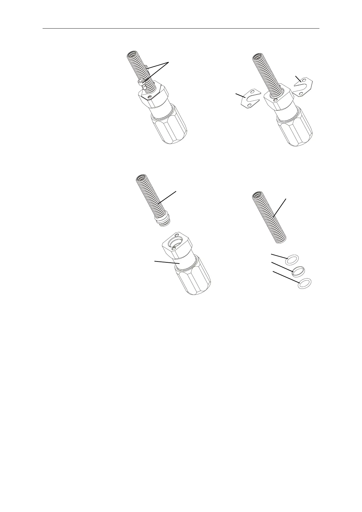
• Unscrew the screws (5) (see diagram 1).
• Push the locking plates (2) to one side (diagram 2)
• Carefully pull the metal hose (1) out of the coupling (4)
(diagram 3).
• Apply lubricant to two new O-rings (1.2) as per L5, and slide the
O-rings and the plastic bushing (1.1) onto the new flexible metal
hose (1) past the first two corrugation valleys (2), leaving the
latter uncovered.
• Apply lubricant to the sealing areas on the flexible metal hose (1)
and the coupling (4) as per L5.
• Lubricate the threads of the junction points as per L4.
• Fit the locking plates (3) on opposite sides of the corrugation
valley immediately following the O-ring (1.2).
• Insert the flexible metal hose (1) together with the locking plates
(3) into the sealing area of the coupling (4) until the locking plates
(3) are in contact with the end of the coupling (4).
Secure the locking plates (3) with two screws (5) and tighten to a
torque of 7 Nm.
5
3
3
diagram 1
diagram 2
1
1
4
diagram 3
1.2
1.1
1.2
diagram 4
 Loading...


