RECONDITIONING
REV6 /REV6 OI 248 (EN) 91
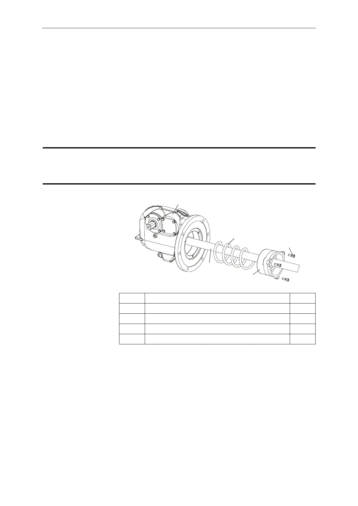
10.2.1 Disassembling the Opening Springs
• Remove the filter cover. Remove the filter sleeve (48) and filter
bag (65) from the crankcase.
• Loosen the three screws (68). To do so, loosen the screws
gradually one by one in order to prevent the spring guide (69)
from tilting.
• Remove the spring guide (69) and opening spring (70) from the
crankcase and carefully pull them off the insulating tube (38).
Reverse the sequence to install the components. Tighten the sc-
rews to a torque of 17Nm. Before remounting the screws, lubricate
them per L1.
In the open state, the precharging travel of the opening
spring is shorter than the thread engagement length of the
screws (68). The screws are therefore used as a releasing
and charging device for the opening springs.
37 Crankcase 1x
38 Insulating tube 1x
68 Socket head cap screw, M8x25 A2-70 3x
69 Spring guide 1x
70 Opening spring 1x
 Loading...


