Installation
Chamber - Column Coup ling
GE Information L31- 7142EN/02
14/18
03- 2017
Final coupling, continued
Fitting the
coupling pin
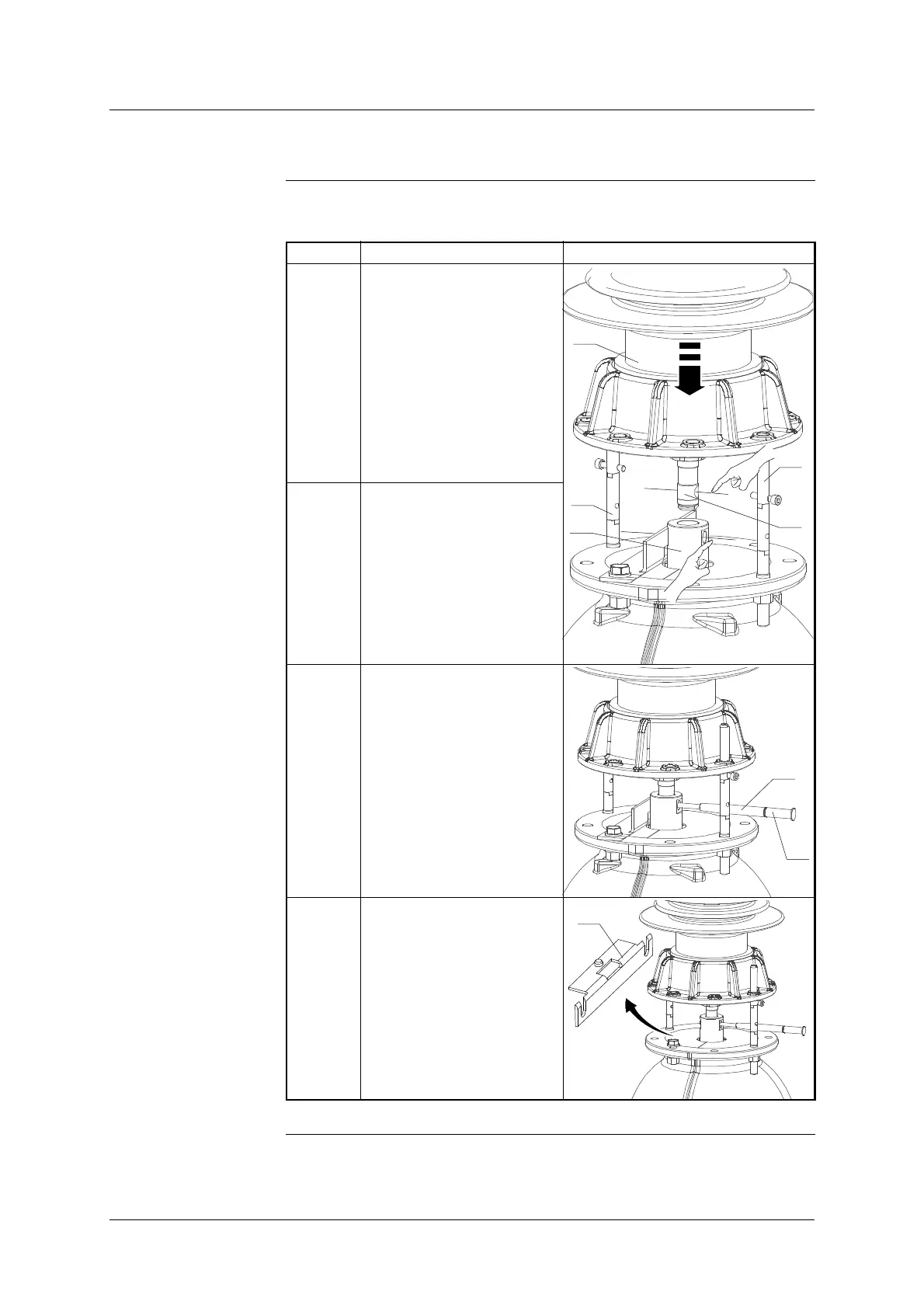
The table below shows the steps for fitting the chamber- column coupling pin:
Step Action Illustration
1 Slowly lower the column (1),
inserting the centring pins
(30) & (31) into the holes in
the flange.
Make sure both pins are cor-
rectly aligned.
1
12
30
8
31
2 Slower lower the column to
align the pin with the holes in
the cylinder (8) and the rod
(12).
3 Insert the fitting tool (35) with
the coupling pin (24) on its
end.
24
35
4 Slightly loosen the two
screws holding the trolley
stop (34) in place and
remove it.
34
Continued on next page.




 To Next Page