– 47 –
The lid switch and the lid lock are both together in
one part.
Lid Lock Assembly Diagnosis
The Lid Switch requires 120 VAC to activate the
locking mechanism. The approximate resistance of
the lock coil is 70 ohms from red-violet at the J513
board connector.
Check the lid switch continuity of the lid switch
between Red and Yellow at the same connector.
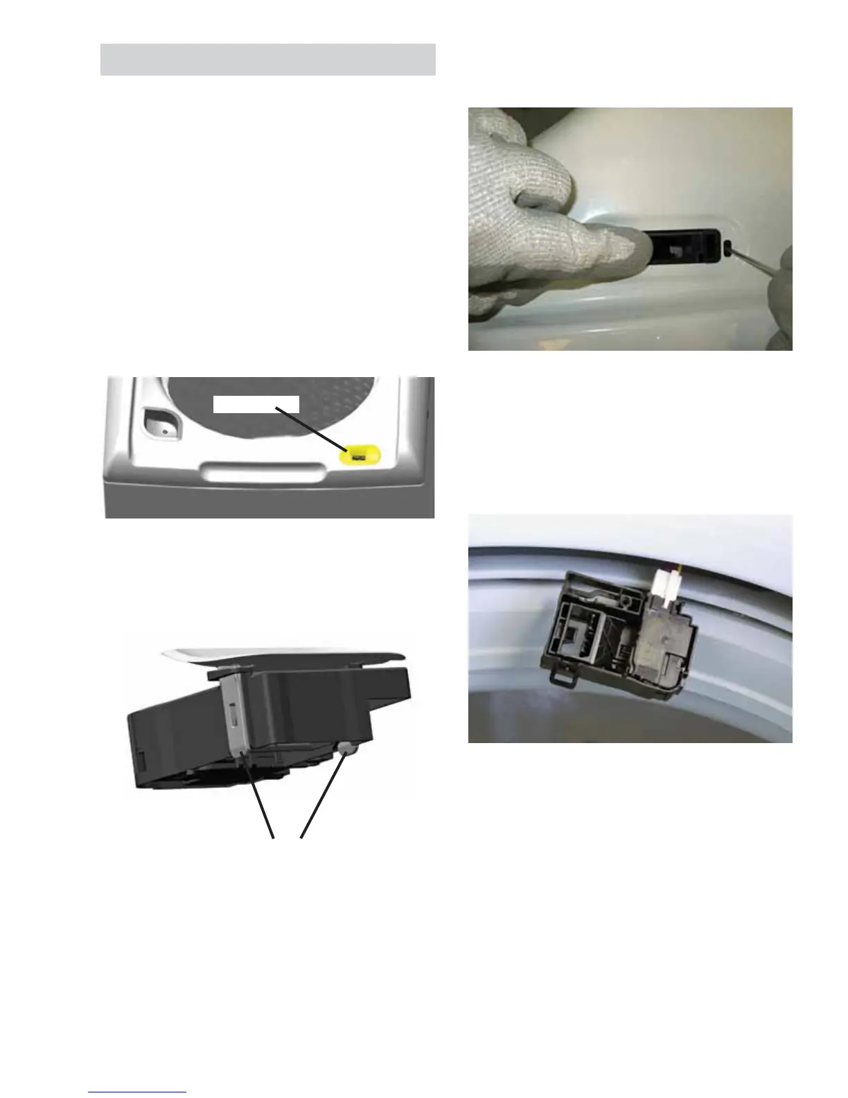
Lid Switch/Lock Assembly Removal
To remove the lid switch/lock assembly, the bezel
ZLOOQHHGWREHUHPRYHG¿UVW
The bezel is held in place by the tabs that extend
through the body of the lock assembly.
1. Reach under the top cover to release the tabs.
Push out and up on the tabs.
2. Using a small screwdriver, push down gently on
the tab that prevents the lock assembly from
moving.
3. 6OLGHWKHORFNDVVHPEO\WRWKHOHIW¿UVWWR
disengage the right lock body tab. Then slide
to the right, allowing the lock assembly to
disengage from the top cover.
4. Slide the lock assembly from under the top cover
and disconnect the harness connector from the
lock assembly.
Lid Switch/Lock Assembly Reinstallation
1. Reconnect the harness connector and slide the
lock assembly into position under the top cover.
2. Bring the left side tab of the lock assembly up
WKURXJKWKHWRSFRYHURSHQLQJ¿UVW
3. Push up on the lock assembly and slide to the
right. This will clip in place.
4. Push the bezel through the top cover securing
the lid switch/lock assembly in position. The
bezel can only go on in one direction. If forced
into position incorrectly, it can damage the lock
assembly.
Lid Switch/Lock Assembly
Bezel
Tabs
 Loading...