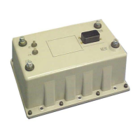
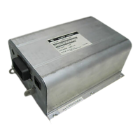
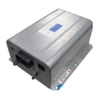
OUTLINE DRAWINGS, ELEMENTARY DRAWINGS AND INPUTS/OUTPUTS
SX TRANSISTOR CONTROL Page 14
Section 3.5 Traction Elementary for Use with a Pump Control (including 1A Contactor)
TMM BRUSHWEAR INPUT
(PUMP CONTROLLER PL2-13)
TMM OVER TEMP
(PUMP CONTROLLER PL2-14)
ACCEL
START
SW.
FWD REV
OSC CARD CONNECTIONS
CONTROL POWER
CONNECTION
POS A1 F1
NEG A2 F2
ARMATURE
A1
A2
SP
+
-
FU1
STEER PUMP
ARM
PUMP CONNECTION
BATT NEG
LINE
FU4
FU3
FU5
PUMP
CONNECTION
POS
L
SP
BDI INTERRUPT
(PUMP CONTROLLER PL2-10)
KEY SWITCH
DIRECT
SWITCH
P18 P17 P2
P6
P4 P5P3
P10
P1
SEAT SW.
A2
A1
TMM7
TMM7
*
*
*
*
*
*
*
*
*
*
MOTOR CONNECTIONS
CUSTOMER SUPPLIED
PY8 PY9
A1
A2
P8
P21
P12
SHIELDED CABLE
P7 P9
*
ACCEL SW.
PY12 PY4 PY5
DASH DISPLAY *
PY11
BRAKE SWITCH*
TYPICAL CONNECTION DIAGRAM FOR USE
WITH A PUMP CONTROLLER (INCLUDING 1A
CONTACTOR)
PUMP
LINE
1A
1A
3
1
2
FIELD
F1
F2
*
P11
PID
P13
SEAT BELT *
Note:
In order for the seat belt switch
input to function properly, a 4.7k
ohm resistor is required in the
truck harness from pin 13 to
negative.
September 2004

 Loading...


