ADJUSTABLE FEATURES
SX TRANSISTOR CONTROLS Page 62
September 2004
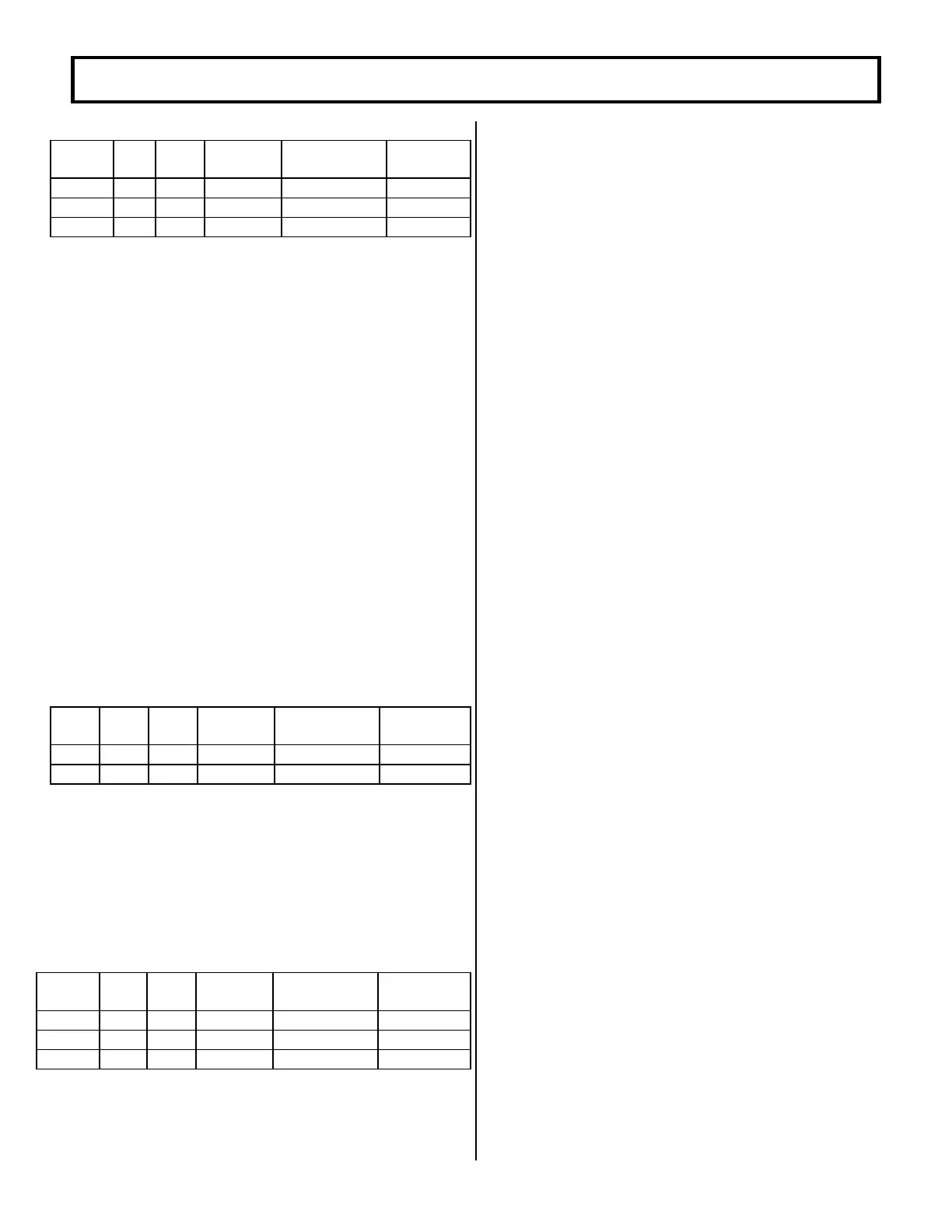
Resolution Example
Rating Min Max Set Per unit value If set at 71
36/48V 0 20 51 to 115 0.314 amps 6.28A
72/80V 0 17 51 to 114 0.269 amps 5.38A
1000A 0 20 51 to 90 0.507 amps 10.14A
MIN I
F
= (VAL-51) X 0.314 ( at 36/48 VOLTS)
MIN I
F
= (VAL-51) X 0.269 ( at 72/80 VOLTS)
MIN I
F
= (VAL– 51) X 0.507 (at 1000 AMPS)
Important Note: This function is used to optimize motor
and control performance, and this setting will be
determined by GE and OEM engineers at the time of
vehicle development. This setting must not be changed by
field personnel without the permission of the OEM.
FUNCTION 8 MAX FIELD CURRENT
( Push 8 )
This function allows for the adjustment of the maximum
field current in order to obtain the maximum torque of the
motor. This function should always be set to 255.
FUNCTION 9 REGEN BRAKING CURRENT LIMIT
(Push 9)
This function allows for the adjustment of the maximum
current seen by the motor during regenerative braking; the
higher the current, the shorter the stopping distance.
Resolution Example
Volts Min Max Set Per unit value If set at 100
36/48 182A 591A 0 to 255 1.625 344 amps
72/80 52A 409A 32 to 255 1.625 162 amps
REGEN BRAKE I
A
= (VAL X 1.625) + 182 at 36/48 volts
REGEN BRAKE I
A
= (VAL X 1.625) at 72/80 volts
FUNCTION 10 MAX FIELD CURRENT DURING REGEN
( Push 10 )
This function allows for the adjustment of the maximum
field current attainable during the regenerative braking
mode.
Resolution Example
Rating Min Max Set Per unit value If set at 220
36/48V 0 64 51 to 255 0.314 53 amps
72/80 0 55 51 to 255 0.269 45 amps
1000A 0 103 51 to 255 0.507 85 amps
I
F
= (VAL-51) x 0.314 (at 36/48 volts)
I
F
= (VAL-51) x 0.269 (at 72/80 volts)
I
F
= (VAL-51) x 0.507 (at 1000 amps)
Important Note: This function is used to optimize motor
and control performance and this setting will be
determined by GE and OEM engineers at the time of
vehicle development. This setting must not be changed by
field personnel without the permission of the OEM.
FUNCTION 11 BRAKE SWITCH CURRENT LIMIT
( Push 11)
This function allows for the adjustment of the maximum
motor armature current when the voltage at Pin 12 is less
than 50% of battery voltage. The 1A contactor will not
close, if the brake switch current is active.
Range 160 amps to 575 amps
Set 0 to 255
Resolution 160 amps + (VALUE x 1.63 amps)
Example Setting of 100 = 323 amps
FUNCTION 12 TOP SPEED LIMIT
( Push 12 )
This function allows for the adjustment of the motor speed
limit (maximum battery volts to the motor). This speed
limit is the same as function 11, however it is always active.
Range 100% to 0% battery volts
Set 46 to 180
Resolution 0.75% per set unit
Example Setting of 80 = 75% of battery volts
SPEED LIMIT = 100% - ((VAL-46) x 0.75%)
FUNCTION 13 MAINTENANCE AND TRUCK
MANAGEMENT SPEED LIMIT
( Push 13 )
This function is the same as function 11, however it is
active based on maintenance hours, or traction motor
overheating or on low BDI value.
Range 100% to 0% battery volts
Set 46 to 180
Resolution 0.75% per set unit
Example Setting of 80 = 75% of battery volts
SPEED LIMIT = 100% - ((VAL-46) x 0.75%)
FUNCTION 14 INTERNAL RESISTANCE
COMPENSATION
( Push 14 )
This function is used when the Battery Discharge Indicator
is present. Adjustment of this function will improve the
 Loading...


