mooring Underthe tige
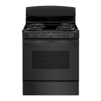
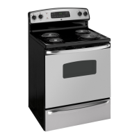
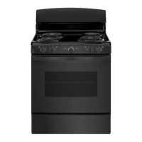
Your range, like many other household
items, is heavyand ~ setie intosofi
floorcoveringssuchas mshionedvinylor
carpeting.
men movingthe range on this type
offlooring,use care and followthese simple and
inexpensiveinstructions.
The range should be installed on a 1/4 inch thick
sheet ofplywood (or similar material) as follows:
Whenthefloor coveting eds at thefront of the
range, the area that the range willrest on should
be builtup with plywoodto the same levelor
higher than the floorcovering.This willallow
the range to be moved for cleaning or servicing.
I STEP2
I
PREPAREFORELECTRIUL CONHE~lON
Use onlya 3<onductor, or ifrequired a 4-
conductor U.L.listed range cord. These cords
may be providedwith ring terminals on wire and
a strain refiefdevice.
A range cord rated at 40
ampswith 125/250
minimumvoltrating is required. A 50 amp range
cord is not recommended but ifused, it should
be marked for use with nominal 1 W diameter
connection openings. Care should be taken to
center cable and strain refiefwithin knockout
hole to keep cablefrom rubbing the edge.
N~: A4<onductor cord is to be used only
when the apphance is installed in a mobilehome
or when localcodes do not permit grounding
through the neutral. Hconduit is being used, go
to WEP 6.
I
STEP3
I POWERCORDSTWH RELIEFIHSTWUTION
A.
Removethe lower rearrange wiring cover to
expose the connector block and bracket.
B. Removethe knockout ring (1%’9located on
bracket directly belowthe connector.To remove
the knockout, use a pair ofpliers to bend the
knockout ring awayfrom the bracket and twist
until ring is removed.
BEFORE
G
KNOCKOUT ‘. O
RING
-1
‘;~:~
BRACKET
a
AFTER
Q
J
- -<J
KNOCKOUT
/\
RING
*
REMOVED
o
C. Assemble the strain rehef in the hole.
Insert the power cord through the strain relief
and tighten. Nlow enough slack to easilyattach
the cord terminals to the connector block. Iftibs
are present at the end ofthe winged strain relief,
they H be removed for better fit.
N~: Do not installthe power cord without a
strain retief.
WIRING COVER
—J
(SHOWN REMOVED)
STRAIN RELIEF
BRACKET (PROVIDED
WITH RANGE CORD.
NOT PARTOF RANGE.)
(continuednmtpage)
31
 Loading...