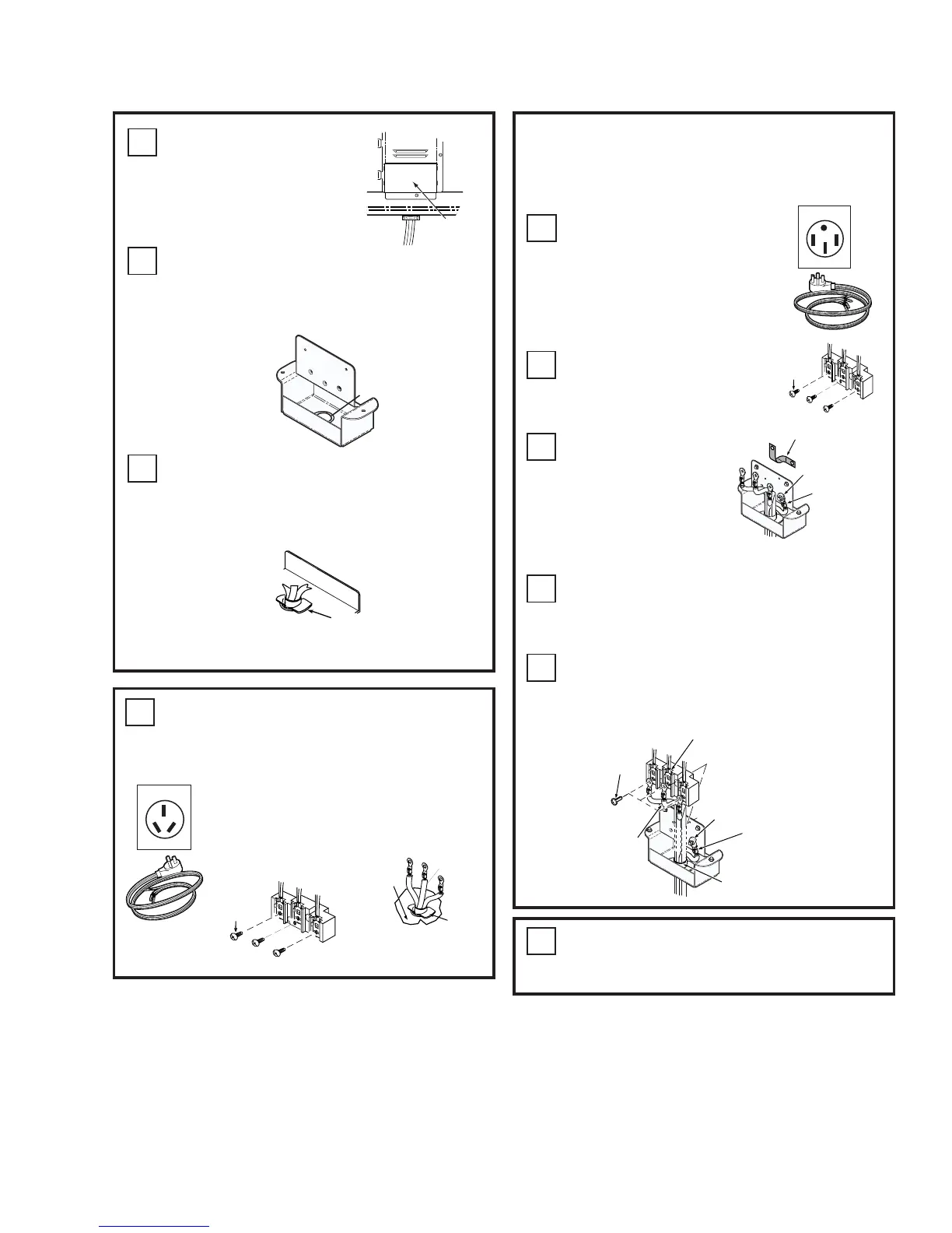
C1
Removewirecoverat
lowerrearofrange.
WIRE COVER
C2
Whenusingapowercord,removethe
knockoutintheconnectionplatewith
pliersasrequiredbythesizeofthe
strainrelieforclampsuppliedwithcord.
Knockout
Terminal
Housing
C3
Insertpowercordthroughholeinthe
terminalhousing,engageandtighten
strainreliefclamp,leavingenoughwire
lengthtoattachterminalstoterminal
block.
C3a
Connection
Plate
Strain
Relief
Clamp
3 wire
cord kit
FOLLOWINSTRUCTIONSBELOWIF
YOURCORDIS3WIRE.
Thepowercordcenterwiremust
beconnectedtomiddleterminal
onblock.Attachremainingwires
securely.Donotremoveground
strap
C5
Re-installthewirecovermakingsure
thewiresdonotbecomepinched
betweenwirecoverandhousing.
50 Amp 4 Wire
C4a
Followinstructions
belowifyourcordis4
wire.
C4b
Removethescrewson
theterminalblock.Do
notremoveterminal
block.
Remove
3 screws
REMOVE & DISCARD
GROUND STRAP
GROUND
WIRE
REUSE
GROUND WASHER
& GROUND SCREW
C4c
Removethe
greenground
screw.Then
removethe
groundstrapand
discardit.
TerminalBlock
C4d
Attachthegreenorbarewirebelowthe
terminalblockwiththegreenground
screwandwasherthatwereremoved
earlier.
C4e
Connecttheredandblackwirestothe
outsideterminals.Thewhitewiremustbe
connectedtothecenterterminal.
OR
Remove
3 screws
Black
White
Red
 Loading...