9
5 DESCRIPTION OF OPERATING SEQUENCE
5.1. Variable power cooking control
High Voltage Inverter Power Supply (U) controls
output power by the signal from Digital Programmer
Circuit (DPC). Power relay stays ON for P3 to P10
and For P1 to P2, both inverter drive signal and power
relay to control output power.
NOTE:
The ON/OFF time ratio does not correspond
with the percentage of microwave power since
approximately 2 seconds are required for
heating of magnetron filament.
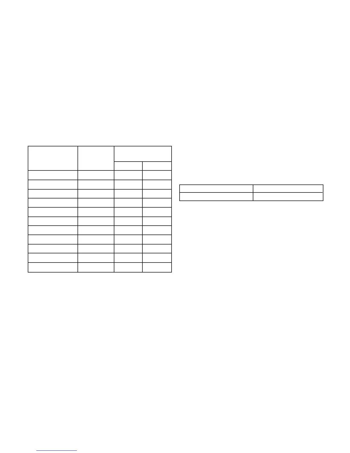
Variable Power Cooking
HIGH P10 100% 22 0
P9 90% 22 0
P8 80% 22 0
MEDIUM-HIGH P7 70% 22 0
MEDIUM P6 60% 22 0
P5 50% 22 0
P4 40% 22 0
MEDIUM-LOW P3 30% 22 0
P2 20% 15 7
P1 10% 8 14
DEFROST P3 30% 22 0
POWER SETTING OUTPUT
POWER(%)
APPROX.
ON-OFF TIME OF
POWER RELAY (RY1)
ON(SEC) OFF(SEC)
5.2. Inverter power supply circuit
NEW H.V.
The Inverter Power Supply circuit powered from the
line voltage, 120V 60Hz AC input supplies 4,000V
DC to the magnetron tube, and functions in place of
the H.V. transformer, the H.V.capacitor and H.V.
diode.
1. The AC input voltage 120V 60Hz is rectified to DC
voltage immediately.
2.
DC voltage will be supplied to the switching devices
called IGBT. These devices are switched ON-OFF
by the 20 to 40 kHz PWM (pulse width modulation)
signal from the microcomputer in the DPC.
3. This drives the High voltage transformer to increase
voltage up to 2,000V AC.
4.
Then the half-wave doubler voltage rectifier circuit,
consisting of the H.V. diodes and capacitors, generates
the necessary 4,000V DC needed for the magnetron.
5. Output power of the magnetron tube is always
monitored by the signal output from the current
transformer built into the inverter circuit.
6. This signal is fed back to the microcomputer in the
DPC to determine operating conditions and output
necessary to control PWM signal to the Inverter
Power Supply for control of the output power.
5.3. Inverter defrost
When the Auto Control feature is selected and the
Start pad is tapped:
1. The digital programer circuit determines the power
level and cooking time to complete cooking and
indicates the operating state in the display window.
Table shows the corresponding cooking times for
respective serving by categories.
Inverter Defrost
SELECTED WEIGHT COOKING TIME
1.0 LB 4 min.45 sec.
2. When cooking time in the display window has
elapsed, the oven turns off automatically by a
control signal from the digital programmer circuit.
5.4. Sensor cooking
Auto sensor cooking without setting a power level or
selecting a time. All that is necessary is to select an
Auto Sensor Program before starting to cook.
Understanding Auto Sensor Cooking
As the food cooks, a certain amount of steam is
produced. If the food is covered, this steam builds up
and eventually escapes from the container. In Auto
Sensor Cooking, a carefully designed instrument,
called the steam sensor element, senses this escape
of steam. Then, based upon the Auto Sensor Program
selected, the unit will automatically determine the
correct power level and the proper length of time it
will take to cook the food.
NOTE:
Auto Sensor Cooking is successful with the
foods and recipes found in the Auto Sensor
Cooking Guide. Because of the vast differences
in food composition, items not mentioned in the
Cooking Guide should be prepared in the
microwave oven using power select and time
features. Please consult Variable Power
Microwave Cookbook for procedures.
 Loading...