Chapter 2: Installation
4 Kilsen KFP-CF Series Installation Manual
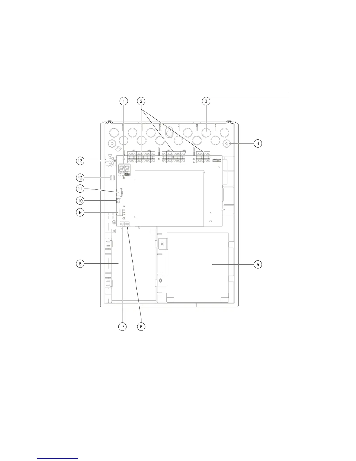
Cabinet layout
Cabinet layout for two- and four-zone control panels
Figure 1: Cabinet layout for two- and four-zone control panels
1. Seven-segment display
2. Zone and fire system connectors
3. Cable knockouts
4. Mounting screw knockouts
5. Battery area
6. Key connector
7. Alarm counter connector
8. Power supply unit
9. Power supply connector
10. Battery connector
11. Expansion module connector
12. Cable holder
13. Fuse terminal block
Note: The alarm counter and key connectors are only included on selected regional
models.
 Loading...