GE Multilin L30 Line Current Differential System 3-37
3 HARDWARE 3.3 PILOT CHANNEL COMMUNICATIONS
3
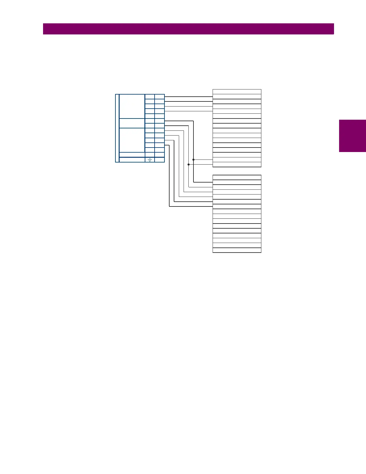
the send timing outputs of data module 1 is also paralleled to the terminal timing inputs of data module 2. By using this con-
figuration, the timing for both data modules and both UR–RS422 channels are derived from a single clock source. As a
result, data sampling for both of the UR–RS422 channels is synchronized via the send timing leads on data module 1 as
shown below. If the terminal timing feature is not available or this type of connection is not desired, the G.703 interface is a
viable option that does not impose timing restrictions.
Figure 3–39: TIMING CONFIGURATION FOR RS422 TWO-CHANNEL, THREE-TERMINAL APPLICATION
Data module 1 provides timing to the L30 RS422 interface via the ST(A) and ST(B) outputs. Data module 1 also provides
timing to data module 2 TT(A) and TT(B) inputs via the ST(A) and AT(B) outputs. The data module pin numbers have been
omitted in the figure above since they vary by manufacturer.
Data module 1
Data module 2
Signal name
Signal name
SD(A) - Send data
TT(A) - Terminal timing
TT(B) - Terminal timing
SD(B) - Send data
RD(A) - Received data
RD(A) - Received data
SD(A) - Send data
SD(B) - Send data
RD(B) - Received data
RD(B) - Received data
RS(A) - Request to send (RTS)
RS(A) - Request to send (RTS)
RT(A) - Receive timing
CS(A) - Clear To send
CS(A) - Clear To send
RT(B) - Receive timing
CS(B) - Clear To send
CS(B) - Clear To send
Local loopback
Local loopback
Remote loopback
Remote loopback
Signal ground
Signal ground
ST(A) - Send timing
ST(A) - Send timing
ST(B) - Send timing
ST(B) - Send timing
RS(B) - Request to send (RTS)
RS(B) - Request to send (RTS)
831022A3.CDR
W
7a
W
2b
W
8a
7W
Shld.
Shld.
Tx1(+)
Tx2(+)
Tx1(-)
Tx2(-)
Rx1(+)
Rx2(+)
+
com
Rx1(-)
Rx2(-)
–
INTER-RELAY COMMUNICATIONS
W
3a
W
5b
W
5a
W
3b
W
2a
W
6a
W
6b
W
7b
W
8b
W
4b
W
4a
RS422
CHANNEL 1
RS422
CHANNEL 2
CLOCK
SURGE