3-32 L30 Line Current Differential System GE Multilin
3.3 PILOT CHANNEL COMMUNICATIONS 3 HARDWARE
3
3.3.3 FIBER-LASER TRANSMITTERS
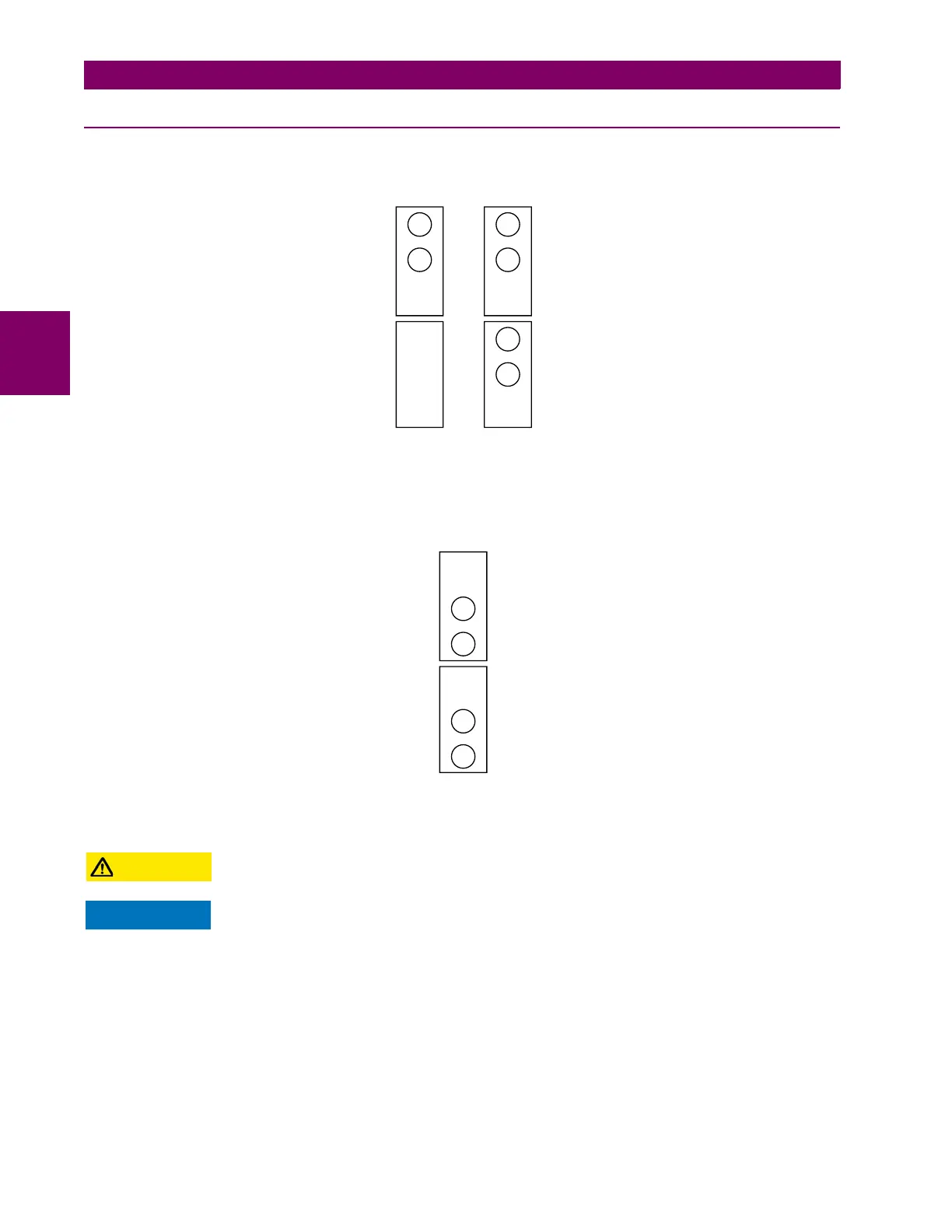
The following figure shows the configuration for the 72, 73, 7D, and 7K fiber-laser modules.
Figure 3–30: 7X LASER FIBER MODULES
The following figure shows configuration for the 2I and 2J fiber-laser module.
Figure 3–31: 2I AND 2J LASER FIBER MODULE
Observing any fiber transmitter output can injure the eye.
When using a laser Interface, attenuators can be necessary to ensure that you do not exceed the
maximum optical input power to the receiver.
1 channel 2 channels
Rx1 Rx1
Rx2
Tx1 Tx1
Tx2
831720A5.CDR
72 and 7D
modules
73 and 7K
modules
2 channels
Tx1
Tx2
Rx1
Rx2
831827A1.CDR
2I and 2J
modules