5-72 L30 Line Current Differential System GE Multilin
5.2 PRODUCT SETUP 5 SETTINGS
5
The AC INPUT WAVEFORMS setting determines the sampling rate at which AC input signals (that is, current and voltage) are
stored. Reducing the sampling rate allows longer records to be stored. This setting has no effect on the internal sampling
rate of the relay which is always 64 samples per cycle; that is, it has no effect on the fundamental calculations of the device.
When changes are made to the oscillography settings, all existing oscillography records are cleared.
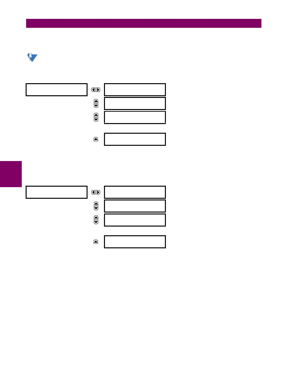
b) DIGITAL CHANNELS
PATH: SETTINGS PRODUCT SETUP OSCILLOGRAPHY DIGITAL CHANNELS
A DIGITAL 1(63) CHANNEL setting selects the FlexLogic operand state recorded in an oscillography trace. The length of each
oscillography trace depends in part on the number of parameters selected here. Parameters set to “Off” are ignored. Upon
startup, the relay will automatically prepare the parameter list.
c) ANALOG CHANNELS
PATH: SETTINGS PRODUCT SETUP OSCILLOGRAPHY ANALOG CHANNELS
These settings select the metering actual value recorded in an oscillography trace. The length of each oscillography trace
depends in part on the number of parameters selected here. Parameters set to “Off” are ignored. The parameters available
in a given relay are dependent on:
• The type of relay,
• The type and number of CT/VT hardware modules installed, and
• The type and number of analog input hardware modules installed.
Upon startup, the relay will automatically prepare the parameter list. A list of all possible analog metering actual value
parameters is presented in Appendix A: FlexAnalog parameters. The parameter index number shown in any of the tables is
used to expedite the selection of the parameter on the relay display. It can be quite time-consuming to scan through the list
of parameters via the relay keypad and display - entering this number via the relay keypad will cause the corresponding
parameter to be displayed.
All eight CT/VT module channels are stored in the oscillography file. The CT/VT module channels are named as follows:
<slot_letter><terminal_number>—<I or V><phase A, B, or C, or 4th input>
DIGITAL CHANNELS
DIGITAL CHANNEL 1:
Off
Range: FlexLogic operand
MESSAGE
DIGITAL CHANNEL 2:
Off
Range: FlexLogic operand
MESSAGE
DIGITAL CHANNEL 3:
Off
Range: FlexLogic operand
↓
MESSAGE
DIGITAL CHANNEL 63:
Off
Range: FlexLogic operand
ANALOG CHANNELS
ANALOG CHANNEL 1:
Off
Range: Off, any FlexAnalog parameter
See Appendix A for complete list.
MESSAGE
ANALOG CHANNEL 2:
Off
Range: Off, any FlexAnalog parameter
See Appendix A for complete list.
MESSAGE
ANALOG CHANNEL 3:
Off
Range: Off, any FlexAnalog parameter
See Appendix A for complete list.
↓
MESSAGE
ANALOG CHANNEL 16:
Off
Range: Off, any FlexAnalog parameter
See Appendix A for complete list.