5-96 L30 Line Current Differential System GE Multilin
5.4 SYSTEM SETUP 5 SETTINGS
5
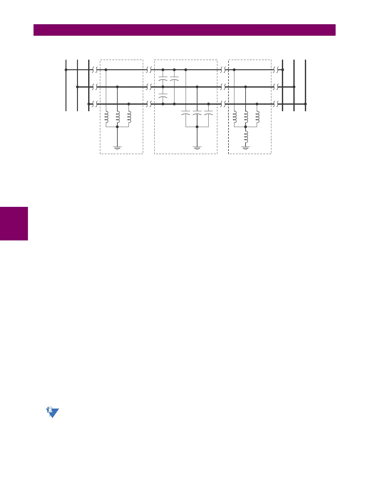
Figure 5–20: CHARGING CURRENT COMPENSATION CONFIGURATIONS
• POSITIVE and ZERO SEQUENCE CAPACITIVE REACTANCE: The values of positive and zero-sequence capacitive
reactance of the protected line are required for charging current compensation calculations. The line capacitive reac-
tance values should be entered in primary kohms for the total line length. Details of the charging current compensa-
tion algorithm can be found in Chapter 8: Theory of operation.
If shunt reactors are also installed on the line, the resulting value entered in the POS SEQ CAPACITIVE REACTANCE and
ZERO SEQ CAPACITIVE REACTANCE settings should be calculated as follows:
1. Three-reactor arrangement: three identical line reactors (X
react
) solidly connected phase to ground:
(EQ 5.7)
2. Four-reactor arrangement: three identical line reactors (X
react
) wye-connected with the fourth reactor (X
react_n
)
connected between reactor-bank neutral and the ground.
(EQ 5.8)
X
1line_capac
= the total line positive-sequence capacitive reactance
X
0line_capac
= the total line zero-sequence capacitive reactance
X
react
= the total reactor inductive reactance per phase. If identical reactors are installed at both line ends, the
value of the inductive reactance is divided by 2 (or 3 for a three-terminal line) before using in the above
equations. If the reactors installed at both ends of the line are different, the following equations apply:
1. For 2 terminal line:
2. For 3 terminal line:
X
react_n
= the total neutral reactor inductive reactance. If identical reactors are installed at both line ends, the
value of the inductive reactance is divided by 2 (or 3 for a three-terminal line) before using in the above
equations. If the reactors installed at both ends of the line are different, the following equations apply:
1. For 2 terminal line:
2. For 3 terminal line:
Charging current compensation calculations should be performed for an arrangement where the VTs are con-
nected to the line side of the circuit; otherwise, opening the breaker at one end of the line will cause a calcula-
tion error.
Possible 3-Reactor
arrangement
Line Capacitive Reactance
Xreact Xreact
Xreact_n
X1line_capac
X0line_capac
Possible 4-Reactor
arrangement
A B C A B C
831731A3.CDR
X
C1
X
1line_capac
X
react
⋅
X
react
X
1line_capac
–
------------------------------------------------
= , X
C0
X
0line_capac
X
react
⋅
X
react
X
0line_capac
–
------------------------------------------------
=
X
C1
X
1line_capac
X
react
⋅
X
react
X
1line_capac
–
------------------------------------------------
= , X
C0
X
0line_capac
X
react
3+ X
react_n
()⋅
X
react
3+ X
react_n
X
0line_capac
–
---------------------------------------------------------------------------------
=
X
react
1
1
X
react_terminal1
-----------------------------------
1
X
react_terminal2
-----------------------------------
+
⁄=
X
react
1
1
X
react_terminal1
-----------------------------------
1
X
react_terminal2
-----------------------------------
1
X
react_terminal3
-----------------------------------
++
⁄=
X
react_n
1
1
X
react_n_terminal1
----------------------------------------
1
X
react_n_terminal2
----------------------------------------
+
⁄=
X
react_n
1
1
X
react_n_terminal1
----------------------------------------
1
X
react__n_terminal2
------------------------------------------
1
X
react_n_terminal3
----------------------------------------
++
⁄=