GE Multilin L30 Line Current Differential System 5-139
5 SETTINGS 5.5 FLEXLOGIC
5
The logic that determines the interaction of inputs, elements, schemes and outputs is field programmable through the use
of logic equations that are sequentially processed. The use of virtual inputs and outputs in addition to hardware is available
internally and on the communication ports for other relays to use (distributed FlexLogic).
FlexLogic allows users to customize the relay through a series of equations that consist of operators and operands. The
operands are the states of inputs, elements, schemes and outputs. The operators are logic gates, timers and latches (with
set and reset inputs). A system of sequential operations allows any combination of specified operands to be assigned as
inputs to specified operators to create an output. The final output of an equation is a numbered register called a virtual out-
put. Virtual outputs can be used as an input operand in any equation, including the equation that generates the output, as a
seal-in or other type of feedback.
A FlexLogic equation consists of parameters that are either operands or operators. Operands have a logic state of 1 or 0.
Operators provide a defined function, such as an AND gate or a Timer. Each equation defines the combinations of parame-
ters to be used to set a Virtual Output flag. Evaluation of an equation results in either a 1 (=ON, i.e. flag set) or 0 (=OFF, i.e.
flag not set). Each equation is evaluated at least 4 times every power system cycle.
Some types of operands are present in the relay in multiple instances; e.g. contact and remote inputs. These types of oper-
ands are grouped together (for presentation purposes only) on the faceplate display. The characteristics of the different
types of operands are listed in the table below.
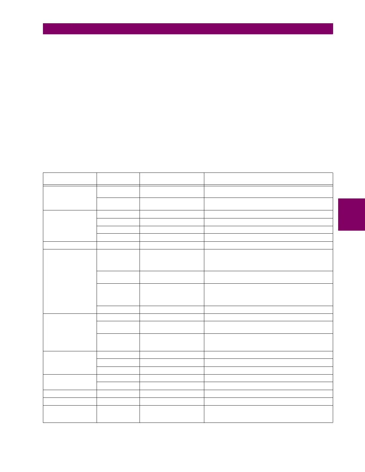
Table 5–16: L30 FLEXLOGIC OPERAND TYPES
OPERAND TYPE STATE EXAMPLE FORMAT CHARACTERISTICS
[INPUT IS ‘1’ (= ON) IF...]
Contact Input On Cont Ip On Voltage is presently applied to the input (external contact
closed)
Off Cont Ip Off Voltage is presently not applied to the input (external
contact open)
Contact Output
(type Form-A contact
only)
Contact Closed Cont Op 1 Closed Contact output is closed
Current On Cont Op 1 Ion Current is flowing through the contact
Voltage On Cont Op 1 VOn Voltage exists across the contact
Voltage Off Cont Op 1 VOff Voltage does not exists across the contact
Direct Input On DIRECT INPUT 1 On The direct input is presently in the ON state
Element
(Analog)
Pickup PHASE TOC1 PKP The tested parameter is presently above the pickup setting
of an element which responds to rising values or below the
pickup setting of an element which responds to falling
values
Dropout PHASE TOC1 DPO This operand is the logical inverse of the above PKP
operand
Operate PHASE TOC1 OP The tested parameter has been above/below the pickup
setting of the element for the programmed delay time, or
has been at logic 1 and is now at logic 0 but the reset timer
has not finished timing
Block PHASE TOC1 BLK The output of the comparator is set to the block function
Element
(Digital)
Pickup Dig Element 1 PKP The input operand is at logic 1
Dropout Dig Element 1 DPO This operand is the logical inverse of the above PKP
operand
Operate Dig Element 1 OP The input operand has been at logic 1 for the programmed
pickup delay time, or has been at logic 1 for this period and
is now at logic 0 but the reset timer has not finished timing
Element
(Digital Counter)
Higher than Counter 1 HI The number of pulses counted is above the set number
Equal to Counter 1 EQL The number of pulses counted is equal to the set number
Lower than Counter 1 LO The number of pulses counted is below the set number
Fixed On On Logic 1
Off Off Logic 0
Remote Input On REMOTE INPUT 1 On The remote input is presently in the ON state
Virtual Input On Virt Ip 1 On The virtual input is presently in the ON state
Virtual Output On Virt Op 1 On The virtual output is presently in the set state (i.e.
evaluation of the equation which produces this virtual
output results in a "1")