GE Multilin L30 Line Current Differential System 5-175
5 SETTINGS 5.6 GROUPED ELEMENTS
5
e) PHASE DIRECTIONAL OVERCURRENT (ANSI 67P, IEC PDOC/PTOC)
PATH: SETTINGS GROUPED ELEMENTS SETTING GROUP 1(6) PHASE CURRENT PHASE DIRECTIONAL 1(2)
The TARGET setting is not user-selectable and forced to "Disabled". If Targets are required from directional
elements, it can be achieved by assigning directional element output to a digital element, where targets
selection can be used as required.
The phase directional elements (one for each of phases A, B, and C) determine the phase current flow direction for steady
state and fault conditions and can be used to control the operation of the phase overcurrent elements via the
BLOCK inputs
of these elements.
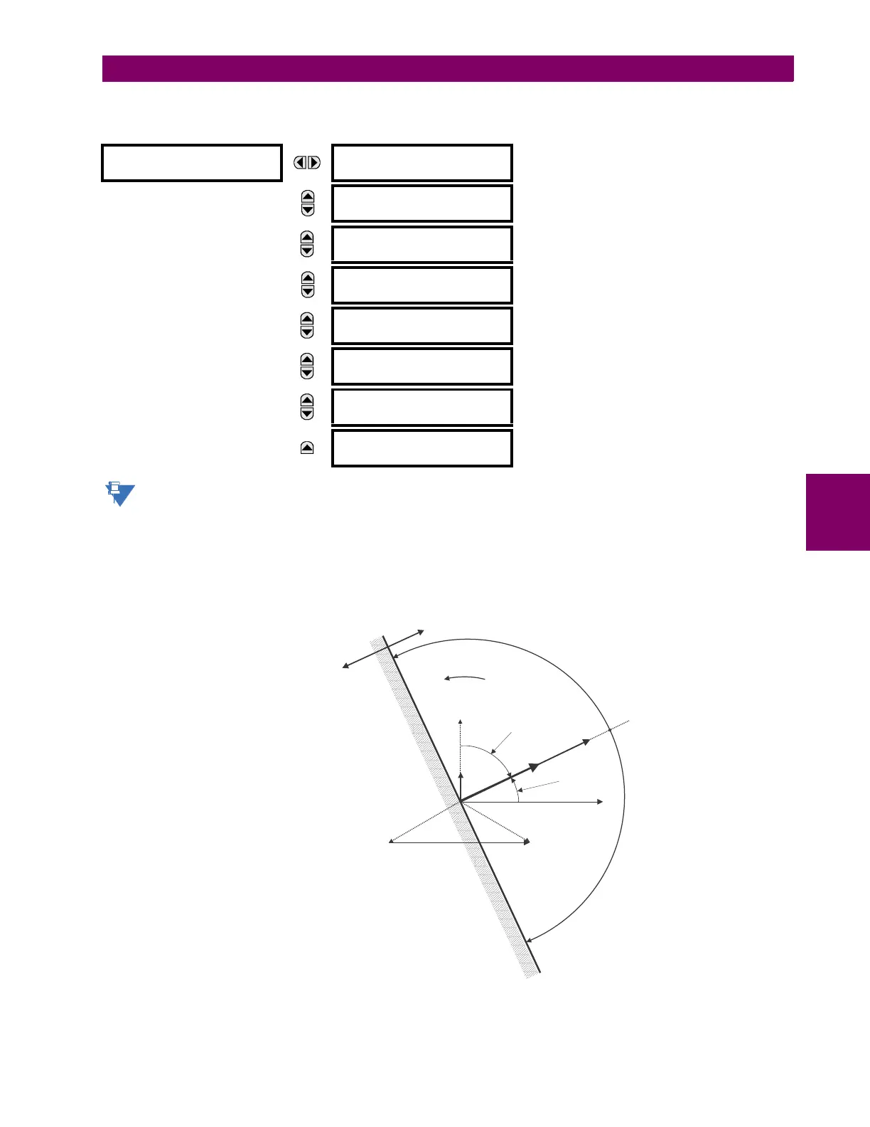
Figure 5–67: PHASE A DIRECTIONAL POLARIZATION
PHASE
DIRECTIONAL 1
PHASE DIR 1
FUNCTION: Disabled
Range: Disabled, Enabled
MESSAGE
PHASE DIR 1 SIGNAL
SOURCE: SRC 1
Range: SRC 1, SRC 2
MESSAGE
PHASE DIR 1 BLOCK:
Off
Range: FlexLogic operand
MESSAGE
PHASE DIR 1
ECA: 30
Range: 0 to 359° in steps of 1
MESSAGE
PHASE DIR POL V1
THRESHOLD: 0.700 pu
Range: 0.000 to 3.000 pu in steps of 0.001
MESSAGE
PHASE DIR 1 BLOCK
WHEN V MEM EXP: No
Range: No, Yes
MESSAGE
PHASE DIR 1
TARGET: Self-reset
Range: Self-reset, Latched, Disabled
MESSAGE
PHASE DIR 1
EVENTS: Disabled
Range: Disabled, Enabled
827800A2.CDR
VBG
VCG
VAG(Faulted)
IA
ECA
set at 30°
ECA = Element Characteristic Angle at 30°
IA = operating current
Phasors for Phase A Polarization:
VPol = VBC (1/_ECA) = polarizing voltage×
Fault angle
set at 60° Lag
VAG (Unfaulted)
OUTPUT
S
0
1
VBC
VBC
VPol
+90°
–90°