5-230 L30 Line Current Differential System GE Multilin
5.7 CONTROL ELEMENTS 5 SETTINGS
5
Setup example shown):
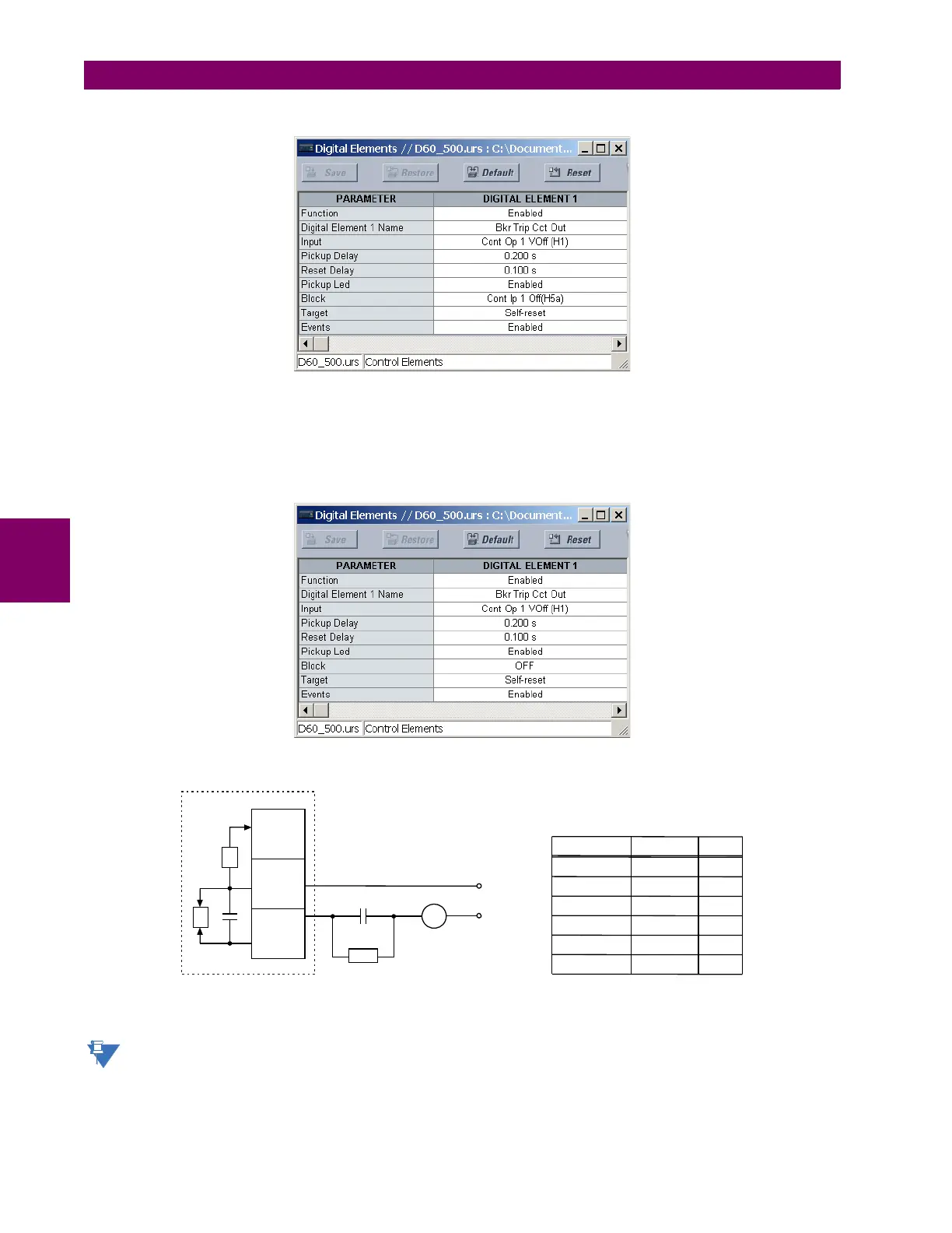
EXAMPLE 2: BREAKER TRIP CIRCUIT INTEGRITY MONITORING
If it is required to monitor the trip circuit continuously, independent of the breaker position (open or closed), a method to
maintain the monitoring current flow through the trip circuit when the breaker is open must be provided (as shown in the fig-
ure below). This can be achieved by connecting a suitable resistor (see figure below) across the auxiliary contact in the trip
circuit. In this case, it is not required to supervise the monitoring circuit with the breaker position – the
BLOCK setting is
selected to “Off”. In this case, the settings are as follows (EnerVista UR Setup example shown).
Figure 5–102: TRIP CIRCUIT EXAMPLE 2
The wiring connection for two examples above is applicable to both form-A contacts with voltage monitoring and
solid-state contact with voltage monitoring.
Trip coil
52a
UR-series device
with form-A contacts
I = current monitor
V = voltage monitor
DC–
827074A3.CDR
H1a
H1b
H1c
I
V
DC+
Bypass
resistor
R
Power supply Resistance Power
24 V DC 1000 O 2 W
30 V DC 5000 O 2 W
48 V DC 10000 O 2 W
110 V DC 25000 O 5 W
125 V DC 25000 O 5 W
250 V DC 50000 O 5 W
Values for resistor “R”