5-236 L30 Line Current Differential System GE Multilin
5.7 CONTROL ELEMENTS 5 SETTINGS
5
c) CT FAILURE DETECTOR
PATH: SETTINGS CONTROL ELEMENTS MONITORING ELEMENTS CT FAILURE DETECTOR(2)
The CT failure function is designed to detect problems with system current transformers used to supply current to the relay.
This logic detects the presence of a zero-sequence current at the supervised source of current without a simultaneous
zero-sequence current at another source, zero-sequence voltage, or some protection element condition.
The CT failure logic (see below) is based on the presence of the zero-sequence current in the supervised CT source and
the absence of one of three or all of the three following conditions.
1. Zero-sequence current at different source current (may be different set of CTs or different CT core of the same CT).
2. Zero-sequence voltage at the assigned source.
3. Appropriate protection element or remote signal.
The CT failure settings are described below.
• CT FAIL 1 FUNCTION: This setting enables or disables operation of the CT failure element.
• CT FAIL 1 BLOCK: This setting selects a FlexLogic operand to block operation of the element during some condition
(for example, an open pole in process of the single pole tripping-reclosing) when CT fail should be blocked. Local sig-
nals or remote signals representing operation of some remote current protection elements via communication chan-
nels can also be chosen.
• CT FAIL 1 3I0 INPUT 1: This setting selects the current source for input 1. The most critical protection element should
also be assigned to the same source.
• CT FAIL 1 3I0 INPUT 1 PICKUP: This setting selects the 3I_0 pickup value for input 1 (the main supervised CT
source).
• CT FAIL 1 3I0 INPUT 2: This setting selects the current source for input 2. Input 2 should use a different set of CTs or
a different CT core of the same CT. If 3I_0 does not exist at source 2, then a CT failure is declared.
• CT FAIL 1 3I0 INPUT 2 PICKUP: This setting selects the 3I_0 pickup value for input 2 (different CT input) of the relay.
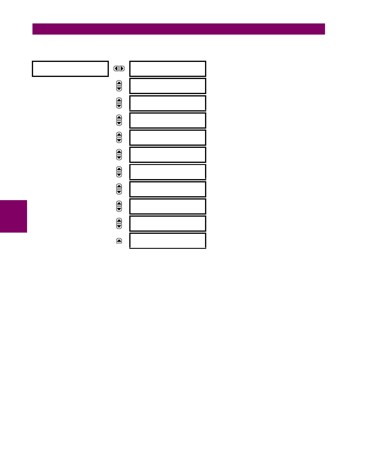
CT FAILURE 1
DETECTOR
CT FAIL 1 FUNCTION:
Disabled
Range: Disabled, Enabled
MESSAGE
CT FAIL 1 BLOCK:
Off
Range: FlexLogic operand
MESSAGE
CT FAIL 1 3I0 INPUT 1:
SRC 1
Range: SRC 1, SRC 2
MESSAGE
CT FAIL 1 3I0 INPUT 1
PKP: 0.2 pu
Range: 0.0 to 2.0 pu in steps of 0.1
MESSAGE
CT FAIL 1 3I0 INPUT 2:
SRC 2
Range: SRC 1, SRC 2
MESSAGE
CT FAIL 1 3I0 INPUT 2
PKP: 0.2 pu
Range: 0.0 to 2.0 pu in steps of 0.1
MESSAGE
CT FAIL 1 3V0 INPUT:
SRC 1
Range: SRC 1, SRC 2
MESSAGE
CT FAIL 1 3V0 INPUT
PKP: 0.20 pu
Range: 0.00 to 2.00 pu in steps of 0.01
MESSAGE
CT FAIL 1 PICKUP
DELAY: 1.000 s
Range: 0.000 to 65.535 s in steps of 0.001
MESSAGE
CT FAIL 1 TARGET:
Self-reset
Range: Self-reset, Latched, Disabled
MESSAGE
CT FAIL 1 EVENTS:
Disabled
Range: Disabled, Enabled