5-242 L30 Line Current Differential System GE Multilin
5.7 CONTROL ELEMENTS 5 SETTINGS
5
• I
B
= protected element base (nominal) current
To ensure element accuracy for high overcurrent conditions, the maximum value of I/(k x I
B
) is limited to 8, even when real-
istically it is exceeding this value.
The reset time of the thermal overload protection element is also time delayed using following formula:
(EQ 5.26)
In the above equation,
• τ
rst
= thermal protection trip time constant
• T
min
is a minimum reset time setting
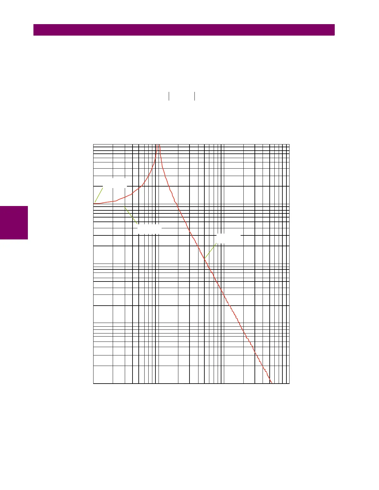
Figure 5–109: IEC 255-8 SAMPLE OPERATE AND RESET CURVES
The thermal overload protection element estimates accumulated thermal energy E using the following equations calculated
each power cycle. When current is greater than the pickup level, I
n
> k × I
B
, element starts increasing the thermal energy:
t
rst
τ
rst
kI
B
()
2
I
2
kI
B
()
2
–
-----------------------------
ln× T
min
+=
0.1
1
10 100
I / I
pkp
t (min)
0.01
0.1
1
10
100
τ = 30
rst
τ = 30
op
T = 10
min
827724A1.CDR