5-268 L30 Line Current Differential System GE Multilin
5.10 TESTING 5 SETTINGS
5
The relay must be in test mode to use the PMU test mode. That is, the TESTING TEST MODE FUNCTION setting must be
“Enabled” and the
TESTING TEST MODE INITIATE initiating signal must be “On”.
During the PMU test mode, the physical channels (VA, VB, VC, VX, IA, IB, IC, and IG), frequency, and rate of change of fre-
quency are substituted with user values, while the symmetrical components are calculated from the physical channels. The
test values are not explicitly marked in the outgoing data frames. When required, it is recommended to use the user-pro-
grammable digital channels to signal the IEEE C37.118 client that test values are being sent in place of the real measure-
ments.
The UR Synchrophasor Implementation defines a test mode which sends a pre-defined set of Synchrophasors out over the
communication channel when the test mode function setting is enabled. In test mode, the following actions take place:
a. The Data Invalid / Test Mode bit (bit 15 in the STAT word) is set.
b. The Sim bit in all output datasets is set.
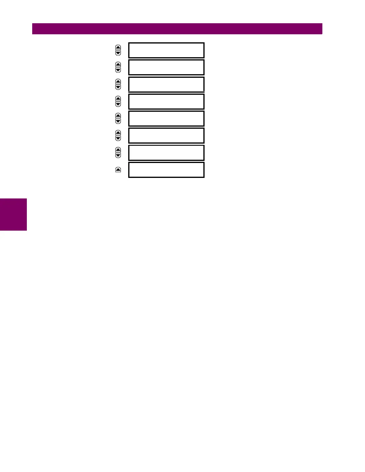
MESSAGE
PMU 1 IB TEST
MAGNITUDE: 1.000 kA
Range: 0.000 to 9.999 kA in steps of 0.001
MESSAGE
PMU 1 IB TEST
ANGLE: –130.00°
Range: –180.00 to 180.00° in steps of 0.05
MESSAGE
PMU 1 IC TEST
MAGNITUDE: 1.000 kA
Range: 0.000 to 9.999 kA in steps of 0.001
MESSAGE
PMU 1 IC TEST
ANGLE: 110.00°
Range: –180.00 to 180.00° in steps of 0.05
MESSAGE
PMU 1 IG TEST
MAGNITUDE: 0.000 kA
Range: 0.000 to 9.999 kA in steps of 0.001
MESSAGE
PMU 1 IG TEST
ANGLE: 0.00°
Range: –180.00 to 180.00° in steps of 0.05
MESSAGE
PMU 1 TEST
FREQUENCY: 60.000 Hz
Range: 20.000 to 60.000 Hz in steps of 0.001
MESSAGE
PMU 1 TEST
df/dt: 0.000 Hz/s
Range: –10.000 to 10.000 Hz/s in steps of 0.001