EasyManuals Logo

GE L30 User Manual

GE L30
698 pages
To Next Page IconTo Next Page
To Previous Page IconTo Previous Page
Page #465 background imageLoading...
Page #465 background image
GE Multilin L30 Line Current Differential System 8-17
8 THEORY OF OPERATION 8.2 OPERATING CONDITION CHARACTERISTICS
8
Figure 8–7: RESTRAINT CHARACTERISTICS
831726A1.CDR
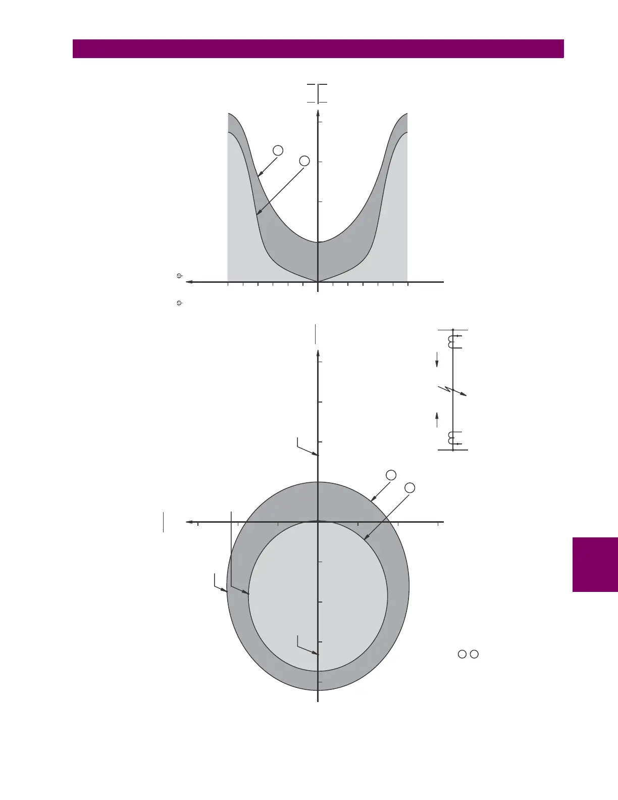
(Angle between loc and rem is
ideally 0 for internal fault)
II
o
1 - For rem =1.5 pu and angle 0-360 with respect to locII
o
2 - For rem =3 pu and angle 0-360 with respect to locII
o
OPERATE
Iloc
Irem
-3
IIloc - rem
180
150
120
90
60
30
-30
-60
-90
-120
-150
-180
1
2
3
4
0
I
I
loc
rem
RESTRAINT
RESTRAINT
1
2
Boundary point (angle between loc and rem about 130 )II
o
Trip point (angle between
loc and rem 0 )II
o
Boundary point (angle between loc and rem about 140 )II
o
OPERATE
1
2
I
I
loc
rem
Imaginary
-2
2
3
1
2
3
4
I
I
loc
rem
Real
-1
-2
Restraint point (angle between
loc and rem 180 )II
o
-3
-4
1
-1
RESTRAINT
0

Table of Contents

Questions and Answers:

Question and Answer IconNeed help?

Do you have a question about the GE L30 and is the answer not in the manual?

GE L30 Specifications

General IconGeneral
BrandGE
ModelL30
CategoryRelays
LanguageEnglish

Related product manuals