Home
GE
Relays
L30
Page 467
GE L30 - Page 467
698 pages
Manual
Save Page as PDF
To Next Page
To Next Page
To Previous Page
To Previous Page
Loading...
GE Multilin
L30 Line Current Differential System
8-19
8 THEORY OF OPERATION
8.2 OPE
RATING CONDITION CHARACTERISTICS
8
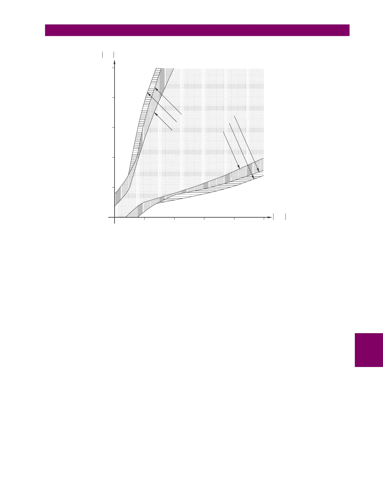
Figure 8–8: SETTINGS IMPACT
ON RESTRAINT CHARACTERISTIC
831725A1.CDR
0
481
2
I
re
m
p
u
OPERATE
RESTRAINT
BP=8,
P=2,
S1=30%,
S2=50%
BP=4,
P=1,
S1=30%,
S2=50%
BP=4,
P=1,
S1=20%,
S2=40%
OPERATE
I
loc
pu
16
20
0
4
8
10
16
20
466
468
Table of Contents
Main Page
Default Chapter
3
Table of Contents
3
1 Getting Started
11
Important Procedures
11
Cautions and Warnings
11
Inspection Procedure
12
Ur Overview
13
Introduction to the Ur
13
Hardware Architecture
13
Software Architecture
14
Enervista Ur Setup Software
15
System Requirements
15
Installation
15
Configuring the L30 for Software Access
16
Using the Quick Connect Feature
19
Connecting to the L30 Relay
24
Setting up Cybersentry and Changing Default Password
25
Ur Hardware
26
Mounting and Wiring
26
Communications
26
Faceplate Display
26
Using the Relay
27
Faceplate Keypad
27
Menu Navigation
27
Menu Hierarchy
27
Relay Activation
28
Relay Passwords
28
Flexlogic Customization
28
Commissioning
29
2 Product Description
31
Introduction
31
Overview
31
Features
33
Security
34
Iec 870-5-103 Protocol
38
Order Codes
39
Overview
39
Order Codes with Enhanced Ct/Vt Modules
39
Order Codes with Process Bus Modules
42
Replacement Modules
47
Signal Processing
49
Ur Signal Processing
49
Pilot Channel Relaying
51
Inter-Relay Communications
51
Channel Monitor
52
Loopback Test
53
Direct Transfer Tripping
53
Specifications
54
Protection Elements
54
User-Programmable Elements
56
Monitoring
57
Metering
58
Inputs
58
Power Supply
59
Outputs
60
Communication Protocols
61
Inter-Relay Communications
61
Environmental
63
Type Tests
64
Production Tests
64
Approvals
65
Maintenance
65
3 Hardware
67
Description
67
Panel Cutout
67
Rear Terminal Layout
73
Wiring
75
Typical Wiring
75
Dielectric Strength
76
Control Power
76
Ct and Vt Modules
77
Process Bus Modules
79
Contact Inputs and Outputs
79
Transducer Inputs and Outputs
91
Rs232 Faceplate Port
93
Cpu Communication Ports
94
Irig-B
96
Pilot Channel Communications
97
Description
97
Fiber: Led and Eled Transmitters
97
Fiber-Laser Transmitters
98
Interface
99
Rs422 Interface
102
Two-Channel Two-Clock Rs422 Interface
104
Rs422 and Fiber Interface
104
And Fiber Interface
105
Ieee C37.94 Interface
105
C37.94Sm Interface
109
4 Human Interfaces
113
Enervista Ur Setup Software Interface
113
Introduction
113
Creating a Site List
113
Enervista Ur Setup Overview
113
Enervista Ur Setup Main Window
115
Extended Enervista Ur Setup Features
116
Settings Templates
116
Securing and Locking Flexlogic Equations
120
Settings File Traceability
122
Faceplate Interface
125
Faceplate
125
Led Indicators
126
Custom Labeling of Leds
129
Display
134
Keypad
134
Breaker Control
134
Menus
135
Changing Settings
137
5 Settings
138
Overview
141
Settings Menu
141
Introduction to Elements
144
Introduction to Ac Sources
145
Product Setup
148
Security
158
Display Properties
164
Clear Relay Records
166
Communications
167
Modbus User Map
204
Real Time Clock
204
Fault Reports
209
Oscillography
211
Data Logger
213
User-Programmable Leds
215
User-Programmable Self-Tests
218
Control Pushbuttons
218
User-Programmable Pushbuttons
221
Flex State Parameters
225
User-Definable Displays
226
Installation
228
Remote Resources Configuration
229
System Setup
230
Ac Inputs
230
Power System
231
Signal Sources
232
Power System
235
Breakers
241
Disconnect Switches
245
Flexcurves
248
Phasor Measurement Unit
255
Flexlogic
278
Introduction to Flexlogic
278
Flexlogic Rules
287
Flexlogic Evaluation
288
Flexlogic Example
288
Flexlogic Equation Editor
293
Flexlogic Timers
293
Flexelements
294
Non-Volatile Latches
299
Grouped Elements
300
Overview
300
Setting Group
300
Line Differential Elements
300
Phase Current
306
Neutral Current
317
Ground Current
325
Negative Sequence Current
327
Breaker Failure (Ansi 50Bf)
330
Voltage Elements
338
Supervising Elements
345
Control Elements
347
Overview
347
Trip Bus
347
Setting Groups
349
Selector Switch
351
Underfrequency (Ansi 81U)
357
Synchrocheck (Ansi 25)
358
Autoreclose (Ansi 79)
362
Digital Elements
368
Digital Counters
371
Monitoring Elements
373
Inputs and Outputs
384
Contact Inputs
384
Virtual Inputs
386
Contact Outputs
387
Virtual Outputs
390
Remote Devices
390
Remote Inputs
392
Remote Double-Point Status Inputs
393
Remote Outputs
393
Direct Inputs and Outputs
394
Resetting
396
Iec 61850 Goose Analogs
396
Iec 61850 Goose Integers
397
Transducer Inputs and Outputs
398
Dcma Inputs
398
Rtd Inputs
399
Dcma Outputs
401
Testing
404
Test Mode
404
Force Contact Inputs
405
Force Contact Outputs
406
Channel Tests
407
Phasor Measurement Unit Test Values
407
6 Actual Values
409
Overview
409
Actual Values Menu
409
Status
409
Contact Inputs
411
Virtual Inputs
411
Remote Inputs
411
Remote Double-Point Status Inputs
412
Direct Inputs
412
Contact Outputs
412
Virtual Outputs
413
Autoreclose
413
Remote Devices
413
Channel Tests
414
Digital Counters
415
Selector Switches
415
Flex States
416
Iec 61850 Goose Integers
416
Ethernet
416
Real Time Clock Synchronizing
417
Remaining Connection Status
418
Parallel Redundancy Protocol (Prp)
418
Metering Conventions
420
Differential Current
423
Sources
424
Synchrocheck
427
Tracking Frequency
428
Flexelements
428
Iec 61580 Goose Analog Values
429
Phasor Measurement Unit
429
Pmu Aggregator
430
Transducer Inputs and Outputs
430
Records
431
Fault Reports
431
Event Records
431
Oscillography
432
Data Logger
432
Phasor Measurement Unit Records
432
Breaker Maintenance
433
Product Information
434
Model Information
434
Firmware Revisions
434
7 Commands and
435
Commands
435
Commands Menu
435
Virtual Inputs
435
Clear Records
435
Set Date and Time
435
Relay Maintenance
437
Phasor Measurement Unit One-Shot
438
Security
439
Targets Menu
440
Target Messages
440
Relay Self-Tests
440
8 Theory of Operation
449
Overview
449
L30 Design
449
L30 Architecture
449
Removal of Decaying Offset
450
Phaselet Computation
450
Disturbance Detection
451
Fault Detection
451
Ground Differential Element
452
Clock Synchronization
453
Frequency Tracking and Phase Locking
454
Frequency Detection
455
Phase Detection
455
Phase Locking Filter
458
Matching Phaselets
459
Start-Up
459
Hardware and Communication Requirements
459
Online Estimate of Measurement Errors
460
Ct Saturation Detection
461
Charging Current Compensation
461
Differential Element Characteristics
462
Relay Synchronization
463
Operating Condition Characteristics
464
Description
464
Trip Decision Example
466
Trip Decision Test
466
Fault Locator
470
9 Application of Settings
471
Ct Requirements
471
Introduction
471
Ct Saturation Analysis Tool
472
Current Differential (87L) Settings
474
Introduction
474
Current Differential Pickup
474
Current Diff Restraint 1
474
Current Diff Restraint 2
474
Current Diff Break Point
474
Ct Tap
475
Channel Asymmetry Compensation Using Gps
477
Description
477
Compensation Method 1
477
Compensation Method 2
478
Compensation Method 3
478
Instantaneous Elements
480
Instantaneous Element Error During L30 Synchronization
480
10 Commissioning
485
Testing
485
Channel Testing
485
Clock Synchronization Tests
486
Current Differential
487
Local-Remote Relay Tests
488
11 Maintenance
489
Modules
489
Replace a Module
489
Batteries
491
Replace Battery
491
Dispose of Battery
493
Uninstall and Clear Files and Data
496
Repairs
497
Storage
498
Disposal
499
Parameter Lists
501
Flexanalog Items
501
A.1.1 Flexanalog Items
501
Flexinteger Items
509
A.1.2 Flexinteger Items
509
Modbus Communications
511
Modbus Rtu Protocol
511
Introduction
511
Physical Layer
511
Data Link Layer
511
B.1.1 Introduction
511
Modbus Rtu Crc-16 Algorithm
512
Modbus Function Codes
514
Supported Function Codes
514
Read Actual Values or Settings (Function Code 03/04H
514
Execute Operation (Function Code 05H
515
Store Single Setting (Function Code 06H
515
Store Multiple Settings (Function Code 10H
516
Exception Responses
516
File Transfers
517
Obtaining Relay Files Via Modbus
517
Memory Mapping
519
Modbus Memory Map
519
Data Formats
582
B.4.2 Data Formats
582
Iec 61850
619
Overview
619
Introduction
619
Communication Profiles
619
C.1.1 Introduction
619
File Transfer by Iec 61850
620
Server Data Organization
621
Overview
621
Ggio1: Digital Status Values
621
Ggio2: Digital Control Values
621
Ggio3: Digital Status and Analog Values from Goose Data
621
Ggio4: Generic Analog Measured Values
621
C.2.1 Overview
621
Mmxu: Analog Measured Values
622
Protection and Other Logical Nodes
622
Server Features and Configuration
624
Buffered/Unbuffered Reporting
624
File Transfer
624
Timestamps and Scanning
624
Logical Device Name
624
Location
624
Logical Node Name Prefixes
625
Connection Timing
625
Non-Iec 61850 Data
625
Communication Software Utilities
625
Generic Substation Event Services: Gsse and Goose
626
Overview
626
Gsse Configuration
626
Fixed Goose
626
Configurable Goose
626
C.4.1 Overview
626
Ethernet Mac Address for Gsse/Goose
629
Gsse ID and Goose ID Settings
629
Iec 61850 Implementation Via Enervista Ur Setup
630
Overview
630
C.5.1 Overview
630
Configuring Iec 61850 Settings
631
About ICD Files
632
Creating an ICD File with Enervista Ur Setup
636
About Scd Files
636
Importing an Scd File with Enervista Ur Setup
639
Acsi Conformance
641
Acsi Basic Conformance Statement
641
Acsi Models Conformance Statement
641
Acsi Services Conformance Statement
642
Logical Nodes
645
Iec 60870-5-103
649
Overview
649
Factor and Offset Calculation to Transmit Measurand
649
D.1.1 Overview
649
Interoperability Document
650
D.1.3 Interoperability Document
650
Interoperability Document
655
E.1.1 Interoperability Document
655
Point List
663
E.1.2 Point List
663
Device Profile Document
665
Dnp V3.00 Device Profile
665
F.1.2 Implementation Table
668
Dnp Point Lists
672
Binary Input Points
672
Binary and Control Relay Output
673
Counters
674
F.2.3 Counters
674
Analog Inputs
675
F.2.4 Analog Inputs
675
Radius Server Configuration
677
Change Notes
679
Revision History
679
Changes to the L30 Manual
679
H.1.1 Revision History
679
Abbreviations
684
Standard Abbreviations
684
H.2.1 Standard Abbreviations
684
H.3.1 Ge Multilin Warranty
687
Warranty
688
Related product manuals
GE L90
900 pages
GE LPS-O
308 pages
GE UR Series L90
846 pages
GE T60
770 pages
GE B90
510 pages
GE 345
82 pages
GE 489
306 pages
GE 369
136 pages
GE P642
592 pages
GE KVGC 202
150 pages
GE UR series
652 pages
GE Multilin 469
64 pages