05-4669A01, Rev. A MDS SD4 Startup Guide 9
• The correct interface between the transceiver and the connected
data equipment (correct cable wiring, proper data format, tim-
ing, etc.)
LED Indicators
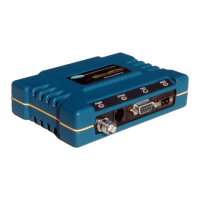
The LED status indicators (Figure 7) are an important troubleshooting
tool and should be checked whenever a problem is suspected. Table 3
describes the function of each status LED on the top panel of the radio.
In addition to the top panel LEDs, the
ETHERNET/LAN connector has
two integrated LEDs. A steady green LED indicates that an Ethernet
link has been established, a flashing green indicates data activity, and
a yellow LED indicates 100 Mbps operation.
Invisible place holder
Figure 7. LED Indicators
Table 3. LED Status Indicators
LED Name Description
PWR • Continuous—Power applied, no problems detected.
• Rapid flash (5 times-per-second)—Fault indication.
LAN • Continuous—Local area network detected.
• Flashing—Data is being transmitted and received.
• Off—LAN not detected or excessive traffic is present.
COM1 and
COM2
COM1 indicator shows activity on the Management/
Diagnostic port of the radio. COM2 indicator shows activity
on the payload data port.
LINK When lit, indicates that a communication link is established
with the master station.
 Loading...