6 MDS SD4 Startup Guide 05-4669A01, Rev. A
Invisible place holder
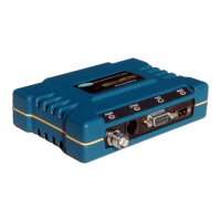
Figure 5. DC Power Connector
The transceiver must be used with negative-ground sys-
tems only. The power supply used with the transceiver
should be equipped with overload protection (NEC
Class 2 rating), to protect against a short circuit between
its output terminals and the radio’s power connector.
Set the radio’s configuration.
The transceiver is designed for
quick installation with a minimum of software configuration
required.
a. Connect a PC to the transceiver’s DB-9
COM1
connector as
shown in Figure 6 using a straight-through cable. Launch a
terminal communications program, such as HyperTerminal
(included with most Windows
systems). Press a
few times to receive the ready “>” prompt on the screen.
Invisible place holder
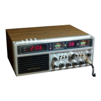
Figure 6. PC Configuration Setup
Lead
Screws (2)
Binding
Wire Ports (2)
(Polarity: Left +, Right –)
Retaining
Screws (2)
CAUTION
POSSIBLE
EQUIPMENT
DAMAGE
ENTER
PC Running Terminal Session
(19,2000 bps, 8N1)
Transceiver
LAN
COM1
COM2
PWR
LINK
To COM1 Port
 Loading...