14 MDS TransNEXT Technical Manual MDS 05-7280A01, Rev. A
2.3 TransNEXT Connectors and Indicators
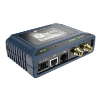
Figure 2-2 shows the unit’s front panel connectors and indicators. These items are referenced in the text
that follows. The unit’s LED Indicator / Button Panel is described in Figure 2-6.
.
Figure 2-2. TransNEXT, Connectors and Indicators
PWR & I/O —Two-conductor DC input connection and I/O
- A latching 6-pin connector is used (Figure 2-3). It is keyed and can only be inserted one way.
- Pin 1 is GND, Pin 5 is Vin.
- Pins 2,4, and 6 are reserved for future I/O capability.
- Use Copper Conductors Only
- Use 18 AWG wire
- Tighten wire clamps to 5 lb-in. (0.6 Nm)
Figure 2-3. 6-pin Power & I/O Connector (P/N 73-1194A85)
Figure 2-4. 6-pin Power & I/O Connector (Phoenix Contact part)
NOTE The unit is designed for use in negative ground DC power systems only. Only use the power
supply provided by the manufacturer for the product or a certified LPS power supply rated for
 Loading...