4 MDS SD Master Station 05-6398A01, Rev. A
c. Click on SDMS Configuration...
d. Redundant radios share a common configuration and are
managed simultaneously through Radio, Security, or
Maintenance and Status...
Note that the links at the top of the page can be used to easily
return to an earlier web page.
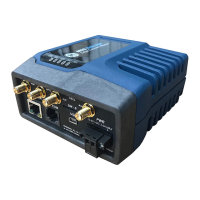
3.2 Configuration via Command Line (CLI)
A scriptable command-line interface is accessible through the
Ethernet port using Secure Shell (SSH) terminal, or through the
unit’s USB interface. For enhanced security, the unit does not sup-
port Telnet configuration. The steps below describe a cabled USB
connection and assume the proper drivers have been installed.
1. Connect a PC to the unit's USB port and establish a console
terminal session using a serial communications program.
2. Press the ENTER key to receive the login prompt. The COM
LED flashes to indicate data communications.
3. Enter the username (admin is the default username) and
press ENTER.
4. At the Password prompt, enter the password (admin is the
default password). Press ENTER. Upon successful login, the
connection message appears.
5. Enter the configuration mode by typing configure followed by
The ENTER key
.
6. Review and configure all key settings for the required applica-
tion. Built-in help is available by pressing the Tab key. A sum-
mary of all unit settings may be viewed by entering the
% show | details command.
Tab-completion is a powerful feature that provides assistance
when typing commands in CLI. Depending on the text that was
already entered, tab-completion displays different possible com-
pletions. When the Tab key is pressed and no text has been
entered, the CLI shows all possible commands that can be typed.
Key items that should be reviewed or set for the unit are as follows:
• Create one-time programmable passwords for unit recovery
• Change login passwords (to maintain security)
• Evaluate default factory configuration and lock the unit down
to the required security level
• Radio configuration, including TX/RX frequency plan
Refer to the Technical Manual for details on the above items.
7. When finished, log out of the console session and disconnect
the PC from the master station.
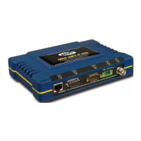
4.0 IN-SERVICE OPERATION
In-service operation of the master station is completely automatic.
The only operator actions required are to apply power and check
the module LEDs for proper indications as shown in Table 4.
Table 4: Module LED Descriptions
Module LED Name Function
PWR and ALARM on (solid) = system initialization (pre-bootup)
5.0 COM1/COM2 REFERENCE
The COM port is commonly used to connect an external DTE
telemetry device to the unit, supporting either the RS-232 or
RS-485 (balanced) format, depending on how the device is config-
ured. The unit supports data rates of 300, 1200, 2400, 4800, 9600,
19200, 38400, 57600, and 115200 bps (asynchronous data only).
This connector mates with a standard RJ-45 plug available from
many electronics parts distributors.
Platform Manager PWR On—Power applied
Flash—System bootup
Platform Manager ALARM Flashing—Alarmed (SD
Master)
Radio PWR/ALARM On—Power applied
Flashing—Alarmed radio
Radio ACTIVE On—Active
Off—Standby
Radio TX On—Transmitting
Radio RX On—Receiving
Alarm/Relay ALARM MAJ On—Major Alarm (SD
Master)
Alarm/Relay ALARM MIN On—Minor Alarm (SD
Master)
Alarm/Relay ACT A On—Radio A Active
Off—Radio A Standby
Alarm/Relay ACT B On—Radio B Active
Off—Radio B Standby