GE MDS, LLC
175 Science Parkway
Rochester, NY 14620
MDS SDA Instruction Sheet Technical Support: +1 585 241-5510
05-6398A01, Rev. A FAX: +1 585 242-8369
September 2014 Web: www.gemds.com
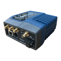
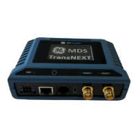
5.1 Pin Descriptions—RS-232 Mode
Pin descriptions for the COM connector in RS-232 mode are
shown in Figure 8 and Table 5. Note that the unit is hardwired as
a DCE device. Refer to the Technical Manual for RS-422/485
descriptions. (Note: RS-485 supported on COM1 only.)
1 2 3 4 5 6 7 8
Figure 8. COM Connector (RJ-45)
As viewed from outside the unit
Table 5: COM1/COM2 Pinouts—RS-232
Pin
#
Input/
Output
Pin Description
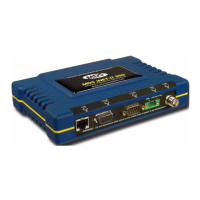
6.0 ALARM/AUDIO PINOUT
The ALARM/AUDIO Interface on the Alarm/Relay module provides
audio signaling and alarm outputs as shown below.
Invisible place holder
Figure 9. Alarm/Audio Connections
(As viewed from outside the radio)
7.0 TROUBLESHOOTING
If trouble occurs with the unit, verify that it meets the basic require-
ments listed below. These items should be checked prior to
starting any detailed troubleshooting or calling for assistance. All
units must have:
• Adequate and stable primary power
• Secure cable and wiring connections
• Proper configuration for the application
7.1 LEDs
The LEDs on the front of installed modules (Table 4) provide useful
information when troubleshooting. Power and alarm indicators are
provided on Platform Manager, Radio, and Alarm/Relay modules.
Radio Modules also have TX/RX LEDs to show wireless activity.
7.2 Redundant Units
The active radio can be identified by the corresponding LED on the
alarm/relay module as well as the active LED on the radio module.
The active unit is normally selected automatically. For trouble-
shooting, the toggle switch can be used to manually set the active
radio. Alternatively, the switch can remain in the automatic posi-
tion, and the active radio can be selected via the SD Manager UI.
7.3 Technical Assistance
Factory technical assistance is available by contacting GE MDS
during business hours (8:30 AM to 6:00 PM Eastern Time). For
telephone assistance, call (585) 241-5510, or visit our website at
www.gemds.com for additional contact options.
Refer also to the Regulatory & Product Information Sheet supplied
with these instructions.
1 Reserved -- (Do not connect)
2 OUT DCD (Data Carrier Detect)
3 Reserved -- (Do not connect)
4 Ground Connects to chassis ground (negative supply)
5 OUT RXD (Received Data)—Supplies received data
to the connected device
6 IN TXD (Transmitted Data)—Accepts TX data
from the connected device
7 OUT CTS (Clear to Send)
8 IN RTS (Request to Send)