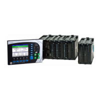
The GE Digital Energy Multilin MX350 is an Automatic Transfer Control System designed for low-voltage power transfer applications. It functions as a modular control and monitoring system, offering flexible control and communication options for various low-voltage transfer switch applications.
Function Description:
The MX350 controls Automatic Transfer Switches (ATS) of different types: Standard (Open) Transition, Delayed Transition, and Closed Transition. It can also manage Bypass/Isolation versions of these ATS types. The system provides comprehensive sensing and control capabilities, depending on the ordered option. It includes expanded diagnostics, high-speed event capture, and a 365-day exerciser. The MX350 features programmable inputs and outputs for additional ATS features and a full complement of programmable ATS control switches (AUTO/MAN, Preferred Source selector, Commit/No Commit Xfer, Transition Mode Select for Closed Transition switch models). For manual operation only, a specific configuration (Option M) is available. The device also supports data logging and waveform capture, with configurable sample periods and triggers. FlexLogic™ is available for user-customized control logic, including interlocking and programmable logic control.
Important Technical Specifications:
General Timing Accuracy:
Protection Specifications:
- Overvoltage:
- Pickup level: 1.05 to 1.10 × VT in steps of 0.01 (programmable)
- Dropout: 1.03 to 1.08 × VT in steps of 0.01 (programmable)
- Time delay: No programmable time delay
- Undervoltage:
- Pickup level: 0.75 to 0.99 × VT in steps of 0.01 (programmable)
- Dropout: 0.85 to 1.00 × VT in steps of 0.01 (programmable)
- Time delay: No programmable time delay
- Overfrequency:
- Pickup level: 50.1 to 63.0 Hz in steps of 0.1 (programmable)
- Dropout: 50.0 to 62.9 Hz in steps of 0.1 (programmable)
- Time delay: No programmable time delay
- Accuracy: ±0.05 Hz
- Underfrequency:
- Pickup level: 45.0 to 59.9 Hz in steps of 0.1 (programmable)
- Dropout: 45.1 to 60.0 Hz in steps of 0.1 (programmable)
- Time delay: No programmable time delay
- Accuracy: ±0.05 Hz
- Power Factor:
- Pickup level: 0.99 lag to 0.99 lead in steps of 0.01 (programmable)
- Dropout: pickup + hysteresis
- Time delay: 0 to 65535 seconds in steps of 1
- Accuracy: ±0.05
- Voltage Imbalance:
- Pickup level: 0.05 to 0.20 in steps of 0.01 (programmable)
- Dropout: 0.03 to 0.18 in steps of 0.01 (programmable)
- Time delay: 1 to 60 seconds in steps of 1
- Current Imbalance:
- Range: 4 to 40% in steps of 1
- Pickup level: 0.04 to 0.40 in steps of 0.01 (programmable)
- Time delay: 1 to 60 seconds in steps of 1 s
- Timing accuracy: ±500 ms
- Elements: alarm
- Accuracy: ±2%
- THD Alarm (Current/Voltage):
- Pickup level: 0.1% to 100.0% in steps of 0.1% (programmable)
- Time delay: 0 to 65535 seconds in steps of 1
- Overcurrent (Per Phase/Neutral):
- Pickup level: 0.01 to 2.00 x Nominal Current in steps of 0.01% (programmable)
- Time delay: 0 to 65535 seconds in steps of 1
User Interface Specifications:
- Graphical Control Panel:
- Size: Height 102mm, width 153mm, depth 35mm
- LCD: 89 mm (3.5-inch) colour, 320 by 240 pixels
- LED indicators: 7 LEDs
- Pushbuttons: Alarm Reset, Test, Ctrl, Info, plus 11 LCD screen display control keys
- Ports: USB 2.0 type Mini-B for laptop computer connection
Metering and Monitoring Specifications:
- Event Recorder:
- Capacity: 256 events
- Data storage: non-volatile memory
- Frequency Metering:
- Range: 40.00 to 70.00 Hz in steps of 0.01
- Accuracy: ±0.05 Hz
- Power Metering:
- Real power range: -2000.0 to 2000.0 kW in steps of 0.1
- Apparent power range: 0.0 to 2500.0 kVA in steps of 0.1
- Accuracy: ±2.0% of full scale with 5 A CT
- Power Factor Metering:
- Range: -0.99 to +0.99 in steps of 0.01
- Accuracy: ±0.05
- Control Voltage Input:
- Input range: 60 V to 300 V AC
- Nominal frequency: 50 or 60 Hz
- Digital Inputs:
- Nominal input voltage: 24 V DC
- Recognition time: 2 cycles
- Continuous current draw: 4 mA
- Type: opto-isolated inputs
- External switch: wet contact
- Phase Current Inputs:
- Range: 2.5 to 7.5 A (1.5 × CT)
- Input type: 5 A
- Frequency: 50 or 60 Hz
- Accuracy: ±2.0% of Full Scale, where Full Scale = 1.5 × CT Primary
- Withstand (at 5A nominal): 0.2 s at 100x, 1.0 s at 50x, 2.0 s at 40x, continuous at 3x rated current
- Phase Voltage Inputs (Three-Phase Voltage):
- Input range: 120 to 600 V (nominal)
- Nominal frequency: 50 or 60 Hz
- Accuracy: ±2% of reading, or ±1 V, whichever is greater
- Note: Phase current Input Type of 1 A is not supported.
Outputs Specifications:
- Form-C Relay:
- Contact material: silver-alloy
- Operate time: 10 ms
- Maximum contact load: 10 mA at 5 V DC
- Maximum switching rate: 300 operations per minute (no load), 30 operations per minute (load)
- Mechanical life: 10 000 000 operations
- Continuous current: 10 A
- Make and carry for 0.2s: 30 A per ANSI C37.90
- Form-C Output Relay Break Capacity:
- AC resistive, 120 V AC: 10 A normally-open, 5 A normally-closed
- AC resistive, 240 V AC: 10 A normally-open, 8 A normally-closed
- AC inductive, PF = 0.4 pilot duty: 2.5 A
- DC resistive, 30 V DC: 10 A
- Solid State Output Relay:
- Operate time: < 1 ms
- Nominal voltage: 24 V DC
- Maximum current: 0.5 A
Power Supply Specifications:
- Power Supply:
- Nominal: 120 to 240 V AC, 125 to 250 V DC
- Range: 60 to 300 V AC (50 and 60 Hz), 84 to 250 V DC
- Ride-Through: 35 ms
- All Ranges:
- Voltage withstand: 2 x highest nominal voltage for 10 ms
- Power consumption: 16 W typical, 25 W maximum
Communications Specifications:
- Ethernet (Copper):
- Modes: 10/100 MB (auto-detect)
- Connector: RJ-45
- SNTP clock synchronization error: <200 ms (typical)
- Protocol: Modbus TCP
- RS485 Port:
- Port: opto-isolated
- Baud rates: up to 115 kbps
- Protocol: Modbus RTU, half-duplex
- Maximum distance: 1200 m
- Isolation: 2 kV
- USB Port:
- Standard specification: Compliant with both USB 2.0 and USB 1.1
- Data transfer rate: USB device emulating serial communications port at 115 kbps
- Connector: USB2.0 Mini-B
Physical Specifications:
- Dimensions:
- Base: 62 mm [2.44"] (W) x 90 mm [3.54"] (H) x 113 mm [4.45"] (D) (+ terminals 10mm [0.39"])
- Expansion: 62 mm [2.44"] (W) x 90 mm [3.54"] (H) x 113 mm [4.45"] (D)
- GCP: 153 mm [6.02"] (W) x 102 mm [4.02"] (H) x 35 mm [1.38"] (D)
- Weight (Base): 0.75 kg [1.65 lb]
Environmental Specifications:
- Ambient Temperatures:
- Storage/shipping: -40°C to 90°C *
- Operating: -20°C to 60°C * (Base Unit and Basic Control Panel), -20°C to 50°C * (Graphical Control Panel)
- *1" around Base Unit
- Humidity: Operating up to 95% (non condensing) @ 55°C (As per IEC60068-2-30 Variant 2, 6days)
- Altitude: 2000 m (max)
- Overvoltage Category: II
- Ingress Protection: IP20 (Base Unit), IP54 (Control Panel)
Usage Features:
The MX350 offers a small footprint and modular design, reducing the number of spare components needed for maintenance and testing. It integrates pushbuttons and LED indicators to minimize external components and wiring. The system supports both DIN rail and panel mounting. Multiple communication protocols (Modbus RTU, Modbus TCP/IP) allow for easy integration into monitoring and control systems. The graphical control panel provides local control and access to system information, featuring a backlit colour LCD screen, 15 pushbuttons, and 7 LED indicators. An EnerVista Launchpad and USB interface facilitate uploading and downloading setup parameters. The device supports 10 customer programmable digital and 10 analog alarms (with Option B). It also includes Auto Load Shed with voltage, frequency, and kW triggers (with Option C).
Maintenance Features:
The modular design of the MX350 allows for easy withdrawal and insertion of modules for fast replacement. Modules must only be replaced in their original factory-configured slots. Proper electrostatic discharge protection is required when handling modules. The product identification label, located on the side panel, provides the product model, serial number, firmware revision, and date of manufacture, which are crucial for maintenance and troubleshooting.