Do you have a question about the GE MM300 and is the answer not in the manual?
General description of the MM300 system and its key benefits.
Safety guidelines to prevent injury and equipment damage.
Detailed safety measures for installation and operation.
Contact information for product support and technical assistance.
Detailed features and capabilities of the MM300 system.
Information on how to specify and order MM300 relay configurations.
Technical specifications including protection, user interface, and power.
Procedures for physical installation, including dimensions and mounting.
Physical dimensions of the MM300 unit for panel mounting and installation.
Methods for mounting the MM300 unit (panel, DIN rail, screw).
Step-by-step guide for safely removing and installing modules.
Guidelines for connecting the MM300 system electrically.
Details on the power supply module and its voltage requirements.
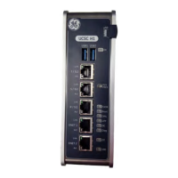
Description of the main CPU module and its connectivity.
Overview of various starter types supported by the MM300.
Overview of the MM300 graphical control panel interface.
Explanation of keypad functions and operations for navigation and control.
Description of the direct control keys (START A, START B, STOP) on the MM300.
Hierarchy and overview of MM300 display pages.
Navigating and accessing configuration, protection, control, and security setpoints.
Overview of diagnostic information like event recorder and counters.
Methods for entering and editing setpoint values.
Functionality and LED indicators of the MM300 basic control panel.
Overview of interfacing with the MM300 using setup software.
Features and capabilities of the EnerVista MM300 setup software.
Steps to resolve issues with the USB driver recognition.
Steps to establish communication between software and the MM300 relay.
Managing setpoints and setpoint files using the setup software.
Procedure for upgrading the MM300 relay firmware.
Capturing and viewing waveforms from the MM300 relay.
Using the data logger feature to sample and record values.
How to access and view measured values.
Overview of metering functions for current, voltage, and power.
Overview of MM300 status messages (trip, alarm, stop).
Details on message types, colors, and navigation.
How to view or alter motor trip and alarm setpoints.
Setpoints for motor configuration, system setup, I/O, and comms.
Overview of various protection elements and their categories.
Details on the MM300's thermal model and its components.
Overview of mechanical protection setpoints.
Overview of electrical protection setpoints.
Programming digital (contact) inputs and their functions.
Configuring contact outputs and assigning functions.
Configuring communication parameters for ports like RS485, Ethernet.
System setpoints including LED behavior and time settings.
Viewing and formatting event lists from the event recorder.
Displaying the values of various MM300 digital counters.
Viewing MM300 waveform parameters and trigger settings.
Accessing diagnostics commands for reset, clearing, and motor info.
Description of the MM300 FlexLogic™ system, operators, and operands.
Available operators in FlexLogic™ and their functions.
Operands related to auto/manual control mode management.
Overview of the MM300's three communication interfaces.
Summary of changes made across different manual revisions.
Details on product warranty periods, limitations, and terms.
Process for returning the device for repair, including RMA and shipping.
| Category | Control Systems |
|---|---|
| Mounting | DIN Rail |
| Model | MM300 |
| Protection | Overload, Short Circuit |
| Communication Protocols | Modbus RTU |
| Efficiency | 90% |
| Protection Features | Overload, Short Circuit |


