2–20 MM300 MOTOR MANAGEMENT SYSTEM – INSTRUCTION MANUAL
ELECTRICAL INSTALLATION CHAPTER 2: INSTALLATION
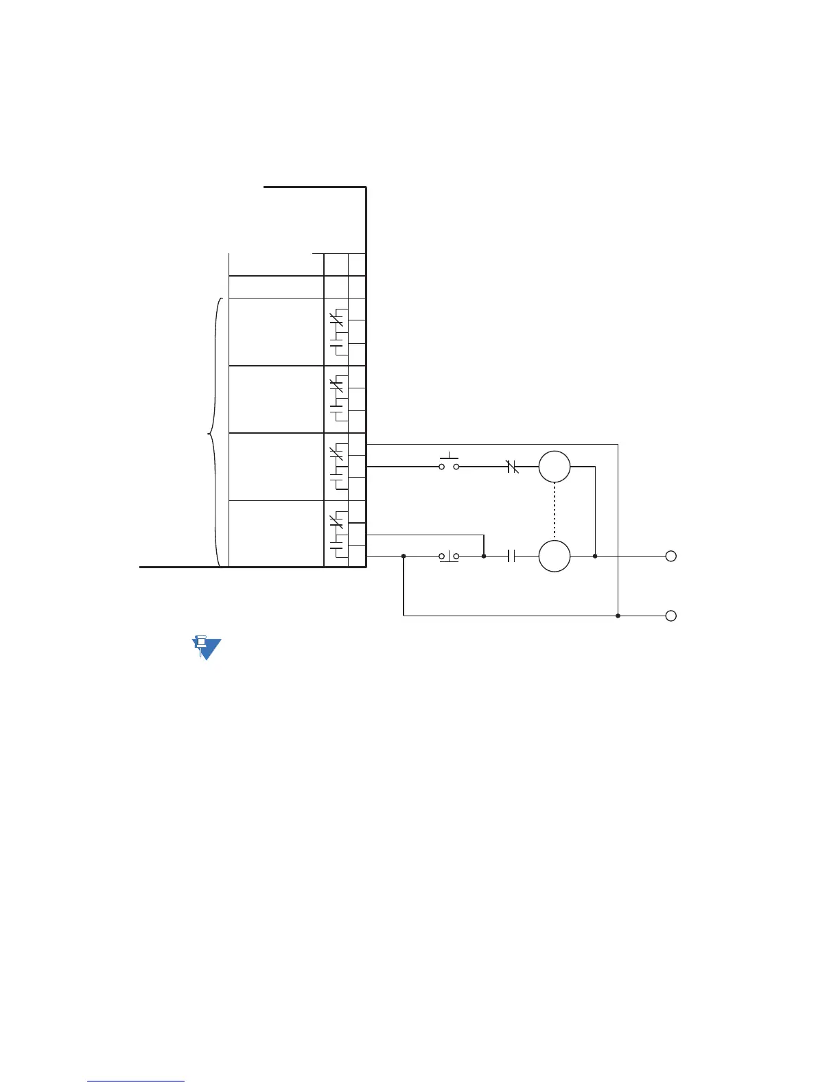
Type IO_D module
connections
The IO_D module contains four form-C contact output relays.
In general, contact outputs can be programmed to follow any one of the digital signals
developed by the MM300, such as alarms and status signals.
Figure 2-24: Typical wiring for type IO_D contact output module
NOTE:
Substitute the slot position of the input/output module (E, F, G, or H) wherever the tilde
symbol “~” appears in the diagrams above.
Control
power
~1
~2
~4
~3
853742A1.CDR
~5
~6
MM300
Motor Management System
~8
~9
~11
~10
~12
~13
~7
~14
Four form-C
contact outputs
CONTACT OUTPUT 1
NOT USED
N
CONTACT OUTPUT 2
CONTACT OUTPUT 3
CONTACT OUTPUT 4
NOT USED
–
STOP
TRIP
COIL
+
START
CLOSE
COIL
52a
52b
L