CHAPTER 2: INSTALLATION ELECTRICAL INSTALLATION
MM300 MOTOR MANAGEMENT SYSTEM – INSTRUCTION MANUAL 2–21
Type IO_E module
connections
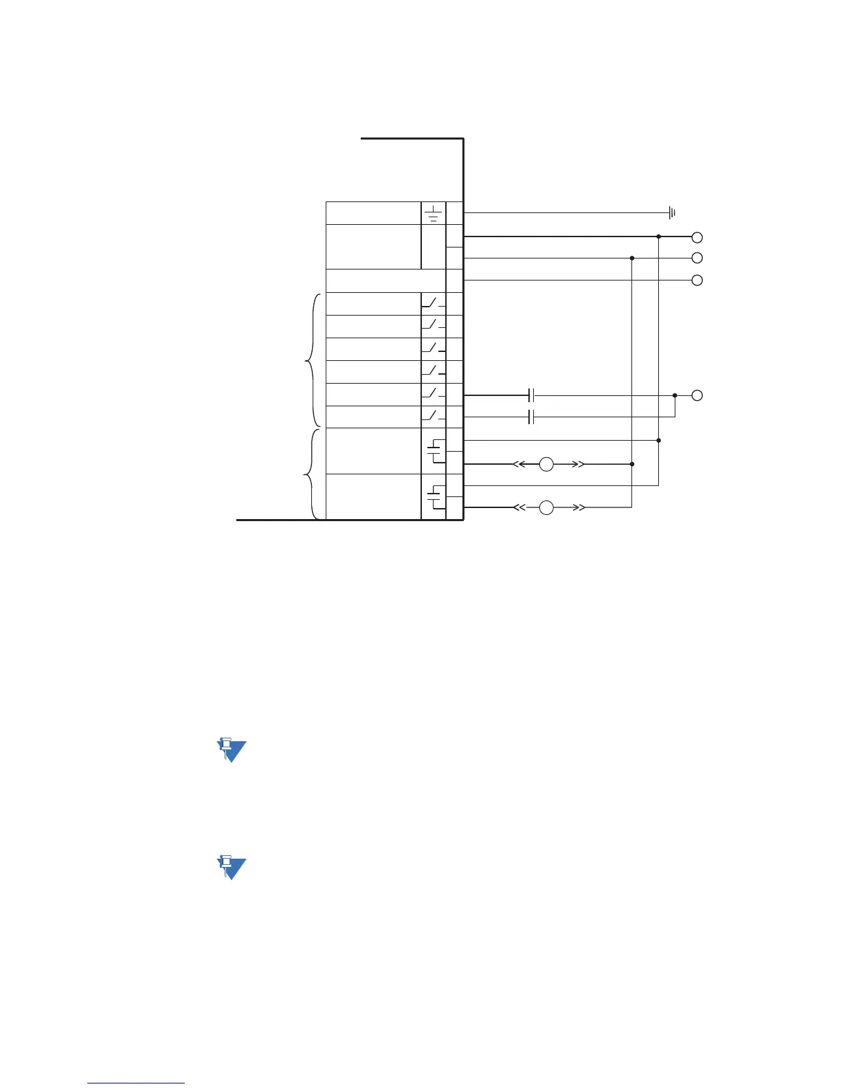
Figure 2-25: Typical wiring for type IO_E module
The IO_E module contains two form-A contact output relays, six digital inputs and a
voltage input, which is a required connection. Contact inputs can be programmed to any
of the input functions, such as field stop or process interlock. The exception is that
contactor A status is fixed as the first contact input, and contactor B status (where used) is
fixed as the second contact input.
An AC auxiliary supply must be connected to terminals 12 and 13 of the IO_E module in
slot C. This auxiliary voltage from slot C is used for actual value indication, for auxiliary
undervoltage, and for undervoltage restart. When three-phase voltages are not available,
it is also used to calculate power quantities and is used as a phase angle reference. When
the IO_E module, located in slot C, senses a low auxiliary voltage inhibit and the
Undervoltage restart function is enabled, the states of the contact inputs are forced to OFF.
NOTE:
The auxiliary voltage connection is required on all IO_E modules, both in slot C and in
expansion slots.
The two contact outputs can be programmed to follow any one of the digital signals
developed by the MM300, such as alarms and status signals. The exception is that the
contactor A relay is fixed as the first contact output, and contactor B relay is fixed as the
second contact output (where used).
NOTE:
Substitute the slot position of the input/output module (C, E, F, G, H) wherever the tilde
symbol “~” appears in the diagrams above.
Contactors
~1
~2
~4
~3
853754A1.CDR
~5
~6
MM300
Motor Management System
~8
~9
~11
~10
~12
~13
~7
~14
Two form-A
contact outputs
CONTACT OUTPUT 2
CONTACT INPUT 1 +
Six contact
(digital) inputs
CONTACT OUTPUT 1
CONTACT INPUT 2 +
CONTACT INPUT 3 +
CONTACT INPUT 4 +
CONTACT INPUT 5 +
CONTACT INPUT 6 +
COMMON
VT INPUT
SURGE
L
N
AC
Control power
–
+
B
A
A
B
DC supply
–
+
DC supply
Contactor Aux