2–12 MM300 MOTOR MANAGEMENT SYSTEM – INSTRUCTION MANUAL
ELECTRICAL INSTALLATION CHAPTER 2: INSTALLATION
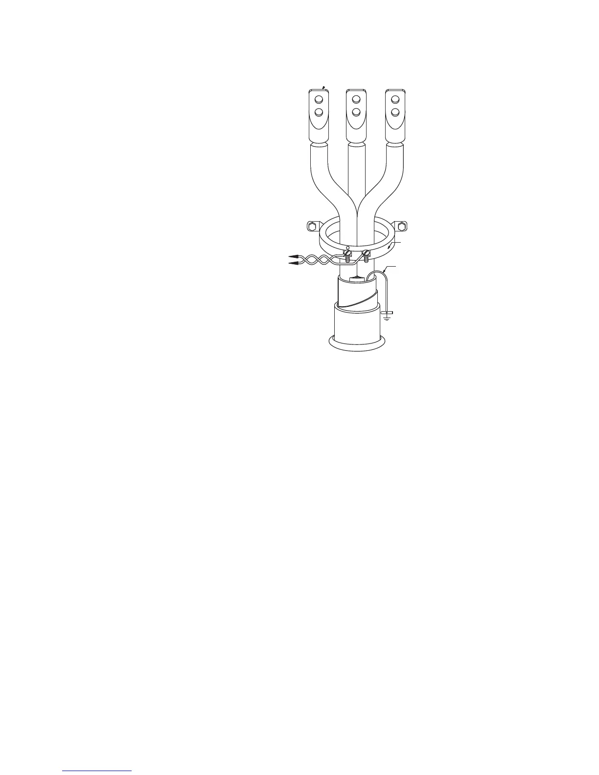
Figure 2-14: Core balance ground CT installation, unshielded cable
Thermistor
connections
Either a positive temperature coefficient (PTC) or negative temperature coefficient (NTC)
thermistor may be directly connected to the + and - terminals on the CPU module. By
specifying the hot and cold thermistor resistance, the MM300 automatically determines
the thermistor type as NTC or PTC. Use thermistors with hot and cold resistance values in
the range 100 to 30000 ohms. If no thermistor is connected, the
Thermistor Alarm and
Thermistor Trip settings must be set to “Disabled”.
POWER CABLE
TO MOTOR
50:0.025 CORE BALANCE CT
FOR GROUND CT SENSING
TO STARTER
GROUND BUS
(TWISTED-PAIR)
853713A1.CDR
GROUND CONDUCTOR DOES
NOT PASS THROUGH CT, AS THE
CT IS NOT MOUNTED OVER
GROUND WITHIN THE CABLE
JACKET.
BOTTOM OF
MOTOR STARTER
COMPARTMENT
CORE BALANCE CT
SECONDARY CONNECTION
TO MM300 IED
 Loading...


