CHAPTER 2: INSTALLATION ELECTRICAL INSTALLATION
MM300 MOTOR MANAGEMENT SYSTEM – INSTRUCTION MANUAL 2–9
NOTE:
It is recommended that you install a circuit disconnection system for control power, near
the device, which should be easily accessible after installation of the unit. This is in case an
emergency power shut-down of the unit is required.
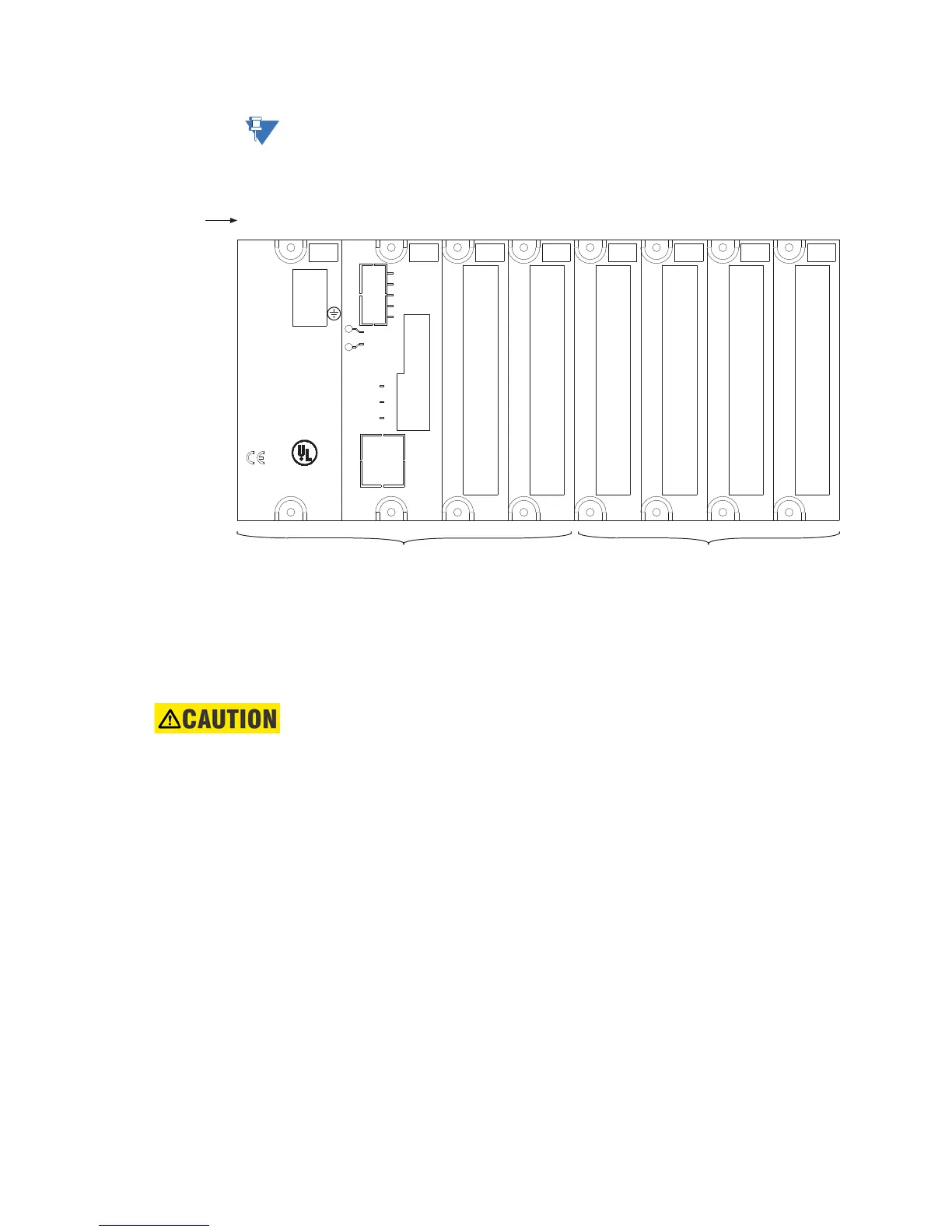
Figure 2-11: Example of module arrangement
Power supply module
The power supply module in slot A supplies control power to the MM300 system. For the
high voltage version, a supply voltage between 60 to 300 V AC or 84 to 250 V DC is required
to power the MM300. For the low voltage version, 20 V DC to 60 V DC is required to power
the MM300.
CAUTION:
Check the voltage rating of the unit before applying control power! Control power
outside of the operating range of the power supply will damage the MM300.
14
13
12
11
10
9
8
7
6
5
4
3
2
1
PSU
60-300 VAC
84-250 VDC
L
gMULTILIN
LISTED
IND.CONT.EQ.
52TL
E200434
Technical Support:
Tel: (905) 294-6222
(North America) 1-800-547-8629
Fax: (905) 201-2098
www.GEMultilin.com
N
MS
NS
THERM RS485
V-
10/100
ETHERNET
GROUND
CT I/P
I
L
C
H
V+
+
–
C
+
–
FIELD BUS
8
7
6
5
4
3
2
1
ABCDE
F
GH
Slot position
Base unit Expansion modules
853749A1.CDR
14
13
12
11
10
9
8
7
6
5
4
3
2
1
14
13
12
11
10
9
8
7
6
5
4
3
2
1
14
13
12
11
10
9
8
7
6
5
4
3
2
1
8
7
6
5
4
3
2
1
R
SG



 To Next Page