CHAPTER 2: INSTALLATION MECHANICAL INSTALLATION
MM300 MOTOR MANAGEMENT SYSTEM – INSTRUCTION MANUAL 2–3
Mounting
The MM300 can be mounted three ways: standard panel mount, DIN rail mount, and screw
mount for high vibration environments.
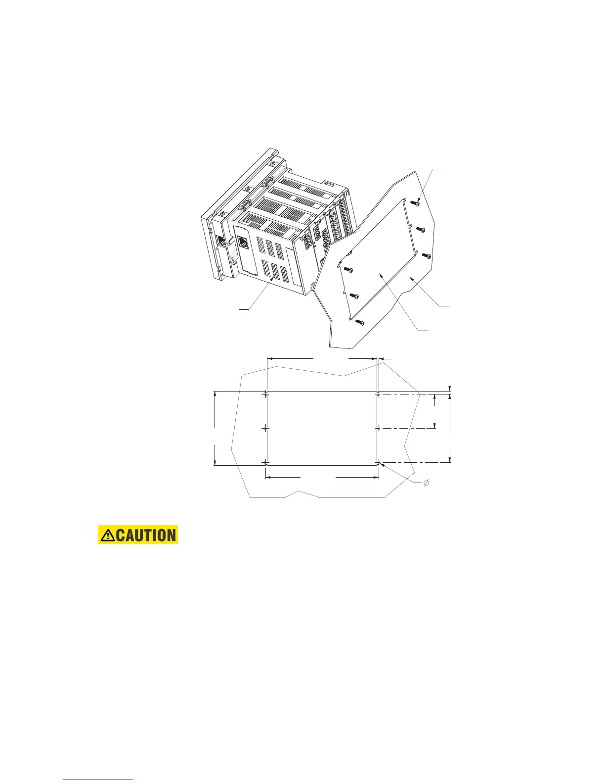
The standard panel mount and cutout dimensions are illustrated below.
Figure 2-3: Base Unit standard panel mounting and cutout dimensions
The DIN rail mounting is illustrated below. The DIN rail conforms to EN 50022.
CAUTION:
To avoid the potential for personal injury due to fire hazards, ensure the unit is
mounted in a safe location and/or within an appropriate enclosure.
#4 - 40x3/8in SELF-TAP PAN HD PHILIPS
QTY: 6 (SUPPLIED); GE PART NO. 1402-0017
TIGHTENING TORQUE: 8 lb-in
REAR OF PANEL
CUTOUT AND
MOUNTING HOLES
INSTALL RELAY
FROM FRONT
OF THE PANEL
3.775”
(95,89 mm)
5.580”
(141,73 mm)
0.105”
(2,67 mm)
0.138”
(3,49 mm)
3.500”
(88,90 mm)
0.130”
(3,30 mm)
(QTY: 6)
5.790”
(147,07 mm)
1.750”
(44,45 mm)
853725A1.CDR



 To Next Page