2–18 MM300 MOTOR MANAGEMENT SYSTEM – INSTRUCTION MANUAL
ELECTRICAL INSTALLATION CHAPTER 2: INSTALLATION
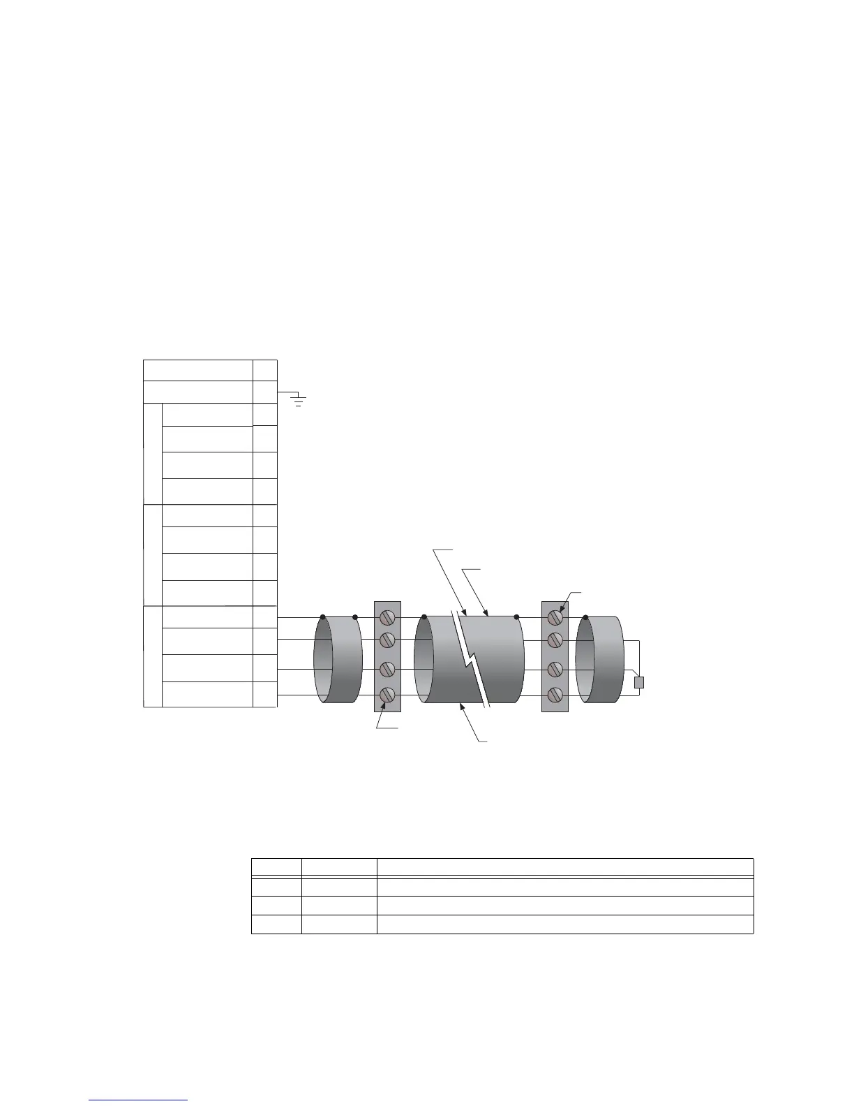
RTD sensor
connections (IO_G
module)
The type IO_G module contains three PT100 RTDs and associated protection functionality.
The MM300 monitors up to six RTD inputs for stator, bearing, ambient, or other
temperature monitoring types. The type of each RTD is 100 ohm platinum (DIN 43760).
RTDs must be three-wire type.
The RTD circuitry compensates for lead resistance, provided that each of the three leads is
the same length. Lead resistance should not exceed 25 ohms per lead. Shielded cable
should be used to prevent noise pickup in industrial environments. RTD cables should be
kept close to grounded metal casings and away from areas of high electromagnetic or
radio interference. RTD leads should not be run adjacent to or in the same conduit as high
current carrying wires.
The uncovered communications cable shield connected to the common terminal should
not exceed 1” (2.5 cm) for proper EMC shielding of the communications cable.
Figure 2-22: RTD wiring
Input/output modules
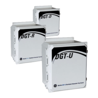
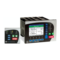
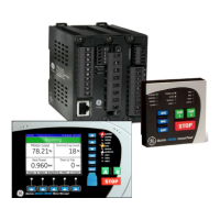
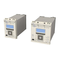
The following input and output modules are available for the MM300.
Table 2-5: MM300 input and output modules
Motor
starter
Motor
Three-wire shielded cable
RTD
terminals in
motor starter
RTD terminals
at motor
Maximum total lead resistance:
25 ohms for Platinum RTDs
Route cable in separate conduit from
current carrying conductors
RTD in motor
stator or
bearing
853737A3.CDR
MM300 Motor Protection System
Surge ground
~13
~4
~3
~2
~1
Compensation
Return
Hot
Shield
RTD1
~8
~7
~6
~5
Compensation
Return
Hot
Shield
RTD2
~12
~11
~10
~9
Compensation
Return
Hot
Shield
RTD3
N/C
~14
Module Slots Description
IO_C C, E, F, G, H Two 10 A form-A relays and six 60 to 300 V AC digital inputs.
IO_D E, F, G, H Four 10 A form-C relays
IO_E C, E, F, G, H Two 10 A form-A relays and six 20 to 60 V DC digital inputs.



 To Next Page