3–8 MM300 MOTOR MANAGEMENT SYSTEM – INSTRUCTION MANUAL
GRAPHICAL CONTROL PANEL CHAPTER 3: INTERFACING WITH THE MM300
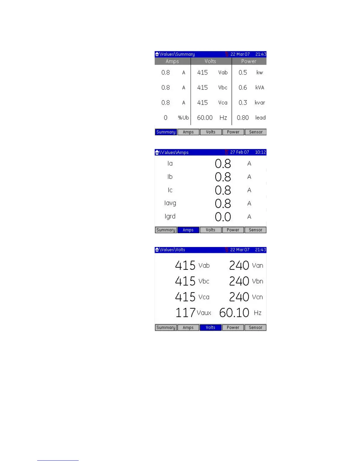
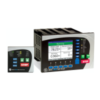
Figure 3-8: Typical actual values summary page
Figure 3-9: Typical actual values current page
Figure 3-10: Typical actual values voltage page
Status pages The status pages provide the user with up-to-date information on the current status of the
MM300.
Status pages are divided into five sections.
• Message (displays all locked out conditions plus conditions such as alarms, internal
faults, control status, etc.).
• Inputs (displays the present state of assigned contact inputs).
• Outputs (displays the present state of assigned contact outputs).
• System (displays the present state of the communications interface).
• Flex (displays the present state of the FlexLogic™ engine and number of lines used.)
A typical display is shown below:



 To Next Page