CHAPTER 2: INSTALLATION MECHANICAL INSTALLATION
MM300 MOTOR MANAGEMENT SYSTEM – INSTRUCTION MANUAL 2–7
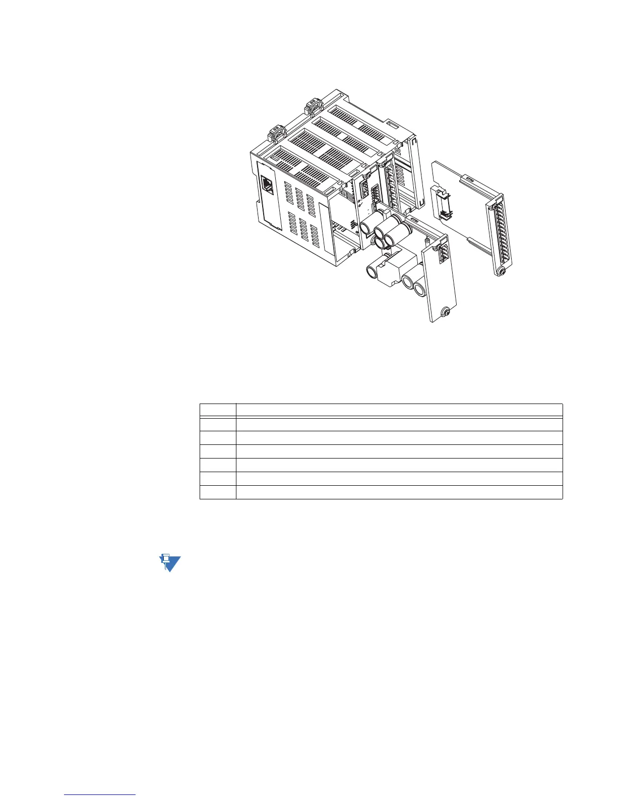
Figure 2-9: Inserting modules into the MM300
Module and terminal identification
The MM300 input/output and protection modules are labeled with the “IO_” prefix followed
by a one-character identifier as follows.
Table 2-1: Input/output module nomenclature
The MM300 terminals are labeled with a three-character identifier. The first character
identifies the module slot position and the second character identifies the terminals within
the module. For example, the first terminal in a module in slot C is identified as “C1”.
NOTE:
Do not confuse the slot designation with the module ordering designation. That is, terminal
“C1” does not imply an IO_C module. Rather, it indicates the first terminal of whatever
module is in slot C.
Module Description
IO_A CT module
IO_B VT module
IO_C Two 10 A form-A relays, six 60 to 300 V AC digital inputs, and Aux VT input module.
IO_D Four 10 A form-C relays module.
IO_E Two 10 A form-A relays, six 20 to 60 V DC digital inputs.
IO_G 3 RTD module.



 To Next Page