CHAPTER 2: INSTALLATION ELECTRICAL INSTALLATION
MM300 MOTOR MANAGEMENT SYSTEM – INSTRUCTION MANUAL 2–13
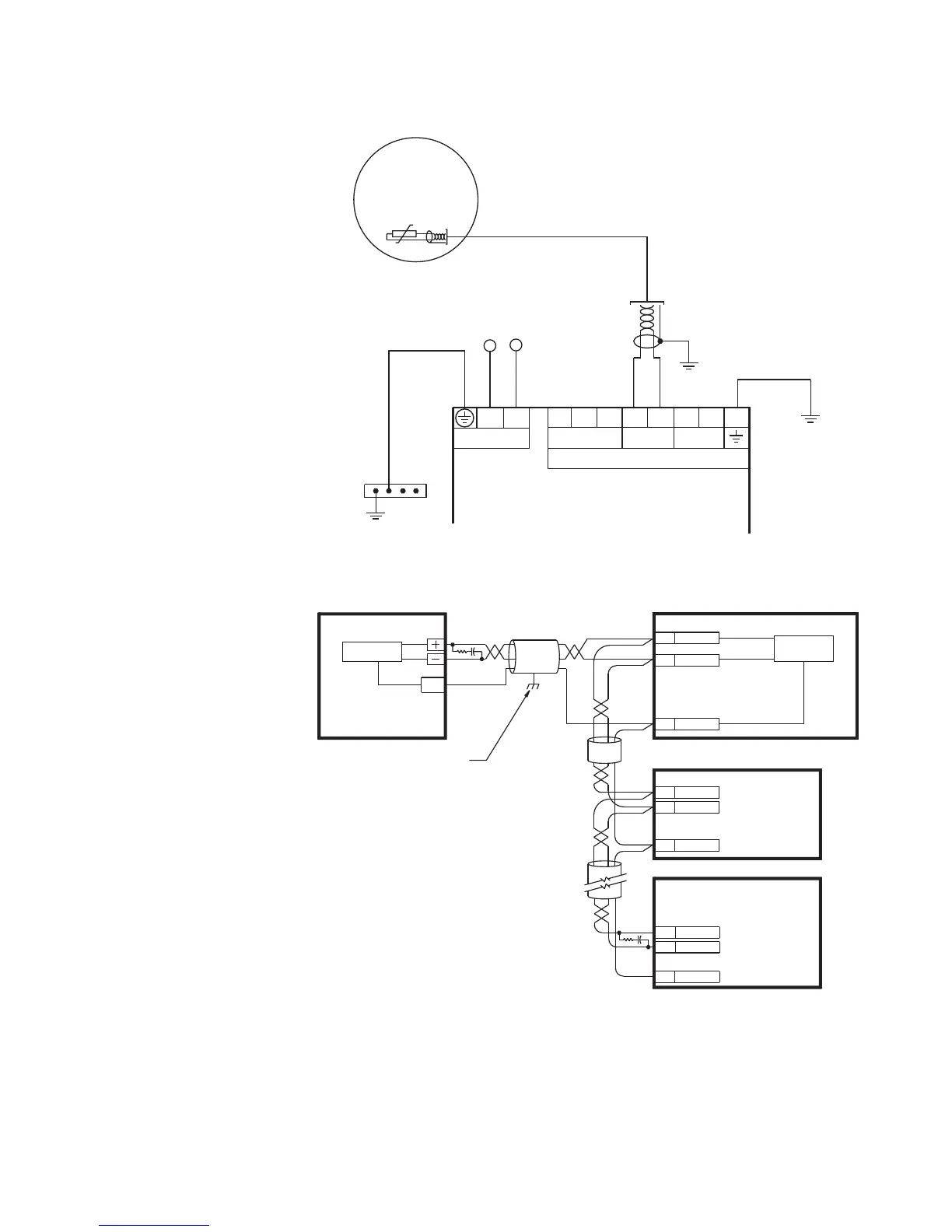
Figure 2-15: Typical thermistor connection
RS485 connections
Figure 2-16: Typical RS485 connection
One two-wire RS485 port is provided. Up to 32 MM300 IEDs can be daisy-chained together
on a communication channel without exceeding the driver capability. For larger systems,
additional serial channels must be added. Commercially available repeaters can also be
used to add more than 32 relays on a single channel. Suitable cable should have a
–
+
–
C–+
CPU module
MM300
Motor Management System
To switchgear
ground bus
853743A1.CDR
R
ISG
RS485 Thermistor CBCT
Control power
LN
+
Stator thermistor
MOTOR
SG = Surge Ground = Functional Ground
SCADA, PLC, OR
PERSONAL COMPUTER
COM
OPTOCOUPLER
DATA
MM300 IED
SHIELD
853745A1.CDR
UP TO 32 MM300
OR OTHER IEDs,
MAXIMUM CABLE
LENGTH OF
1200 m (4000 ft.)
LAST
DEVICE
(*) TERMINATING IMPEDANCE AT EACH END
(typically 120 ohms and 1 nF)
TWISTED PAIR
Z
T
(*)
RS485 +
RS485 -
COMMON
RS485 +
RS485 -
COMMON
IED
RS485 +
IED
RS485 -
COMMON
GROUND THE SHIELD AT THE
SCADA/PLC/COMPUTER ONLY
OR THE MM300 ONLY
DATA
OPTOCOUPLER
B1
B2
B3
Z
T
(*)