Instruction Manual
© GE Grid Solutions
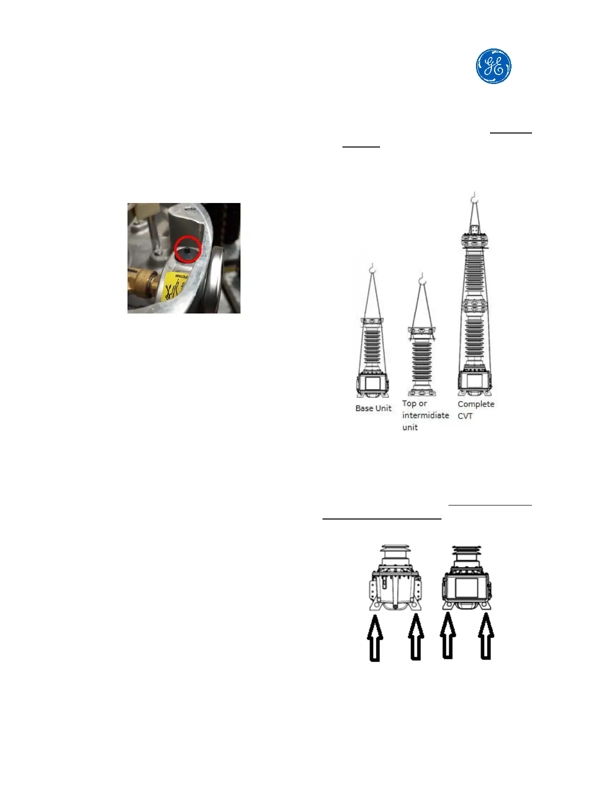
all OTCF models, this small protrusion
needs to be cut after the
transportation. For the cases when CD
units are transported at horizontal
position, cut the protrusion only after
putting the CD at vertical position.
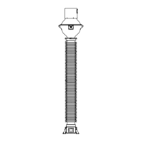
Follow the steps below for mounting on
the pedestal:
Place the CD top modules with their
nameplates aligned to the main
nameplate, installed on the
secondary terminal box cover in the
base tank.
Place each module slowly, one at a
time, with a crane.
Place the bolts in the upper unit
flange holes.
Fasten the bolts with an appropriate
torque (3 kgf.m).
Repeat the same procedure for all
subsequent upper modules.
ATTENTION! It is mandatory for the
serial numbers of the CD modules to
match the serial number shown on the
CVT main nameplate. Accuracy and
ferroresonance performance will be
affected if incorrect capacitive modules
are assembled together.
The serial reactance and transformer
ratio are adjusted and tuned during the
factory routine tests to meet the
specified accuracy class. Each EMU is
tuned to a CD. In this way, it is not
allowed to exchange any CD module or
even a complete CD from one EMU to
another.
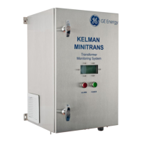
Example of lifting
The base unit (or unit with only 1 module)
must be handled using the 04 lifting holes
available in the base tank. The use of the 04
lifting holes is mandatory.
4 lifting eyes