Instruction Manual
© GE Grid Solutions
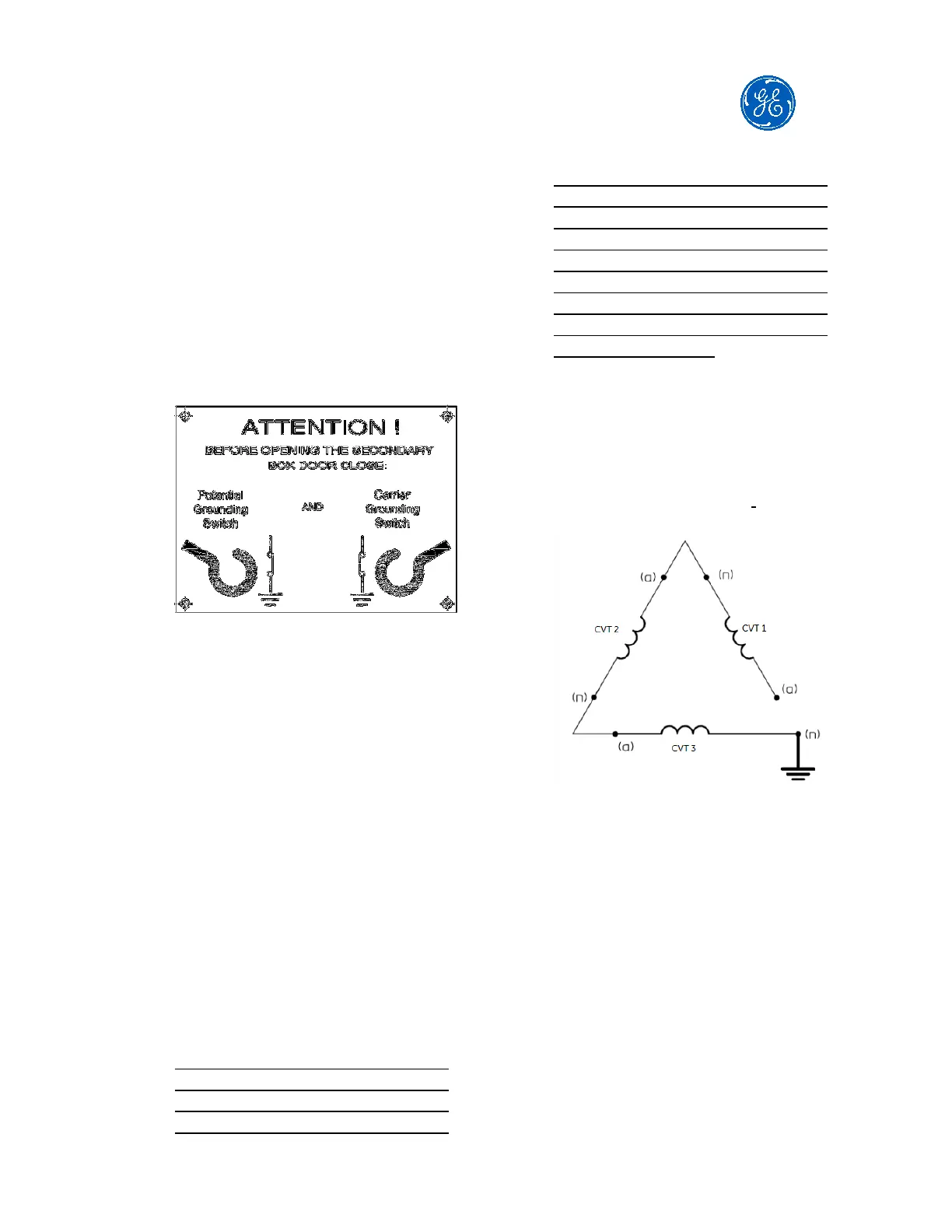
5.2. Secondary terminal box
Before opening the secondary
terminal box, check the position of
the EMU and carrier grounding
switches. A warning plate is supplied
with the CVT and is placed on the
secondary terminal box on the side of
the potential grounding switch.
5.3. Secondary terminals
Look for the set of drawings of the
CVT to verify the type of connection
to the secondary terminal and
acceptable cables for the connection.
Use proper connectors to ensure a
good connection. Tightening torque is
indicated on the secondary terminal
box drawing.
One point of each secondary should
be connected to the ground terminal
inside the secondary terminal box, in
order to obtain a ground point for the
potential reference.
Unused secondary terminals must
remain open circuit and one point of
the unused secondary terminal must
be connected to the ground terminal.
This grounding should be done at
one point only, as far away as
possible from the CVT, preferably in
the control room. Multiple grounding
points may cause transient voltage
difference that can cause circulation
of surge currents between windings,
rather than flowing from the
windings to the earth.
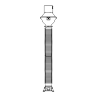
When a secondary winding is used in
a broken delta connection with
secondary windings of CVT from other
phases, ensure that there is only one
grounding point on the broken delta
connection as shown below.
NEVER SHORT CIRCUIT THE
SECONDARY TERMINAL OF A
CVT
.
5.4. HF terminal
When available, for connection to the
carrier system, connect the lead-in
cable through the removable
undrilled gland plate of the secondary
terminal box to the 'HF' terminal. The
figure below shows the typical
position of the 'HF' terminal. Confirm
the position of this terminal in the
CVT secondary terminal box.