Instruction Manual
© GE Grid Solutions
1. SCHEMATIC DIAGRAM
The OTCF Capacitor Voltage Transformer (CVT) is an assembly of a capacitive voltage divider (CD)
and an electromagnetic unit (EMU). Depending on the rated voltage, the CD may contain of one or
more capacitive modules with an intermediate voltage terminal through a medium voltage
bushing which feeds the EMU.
Each capacitive module contains capacitive elements impregnated with synthetic oil and is
hermetically sealed, a metallic bellows works as expansion chamber to compensate variation of
volume of oil due to ambient temperature changing.
When specified, each capacitive module can be supplied with a manometer for indication of
internal pressure of oil.
The EMU is mounted in a tank filled with mineral oil and is hermetically sealed through an air
cushion.
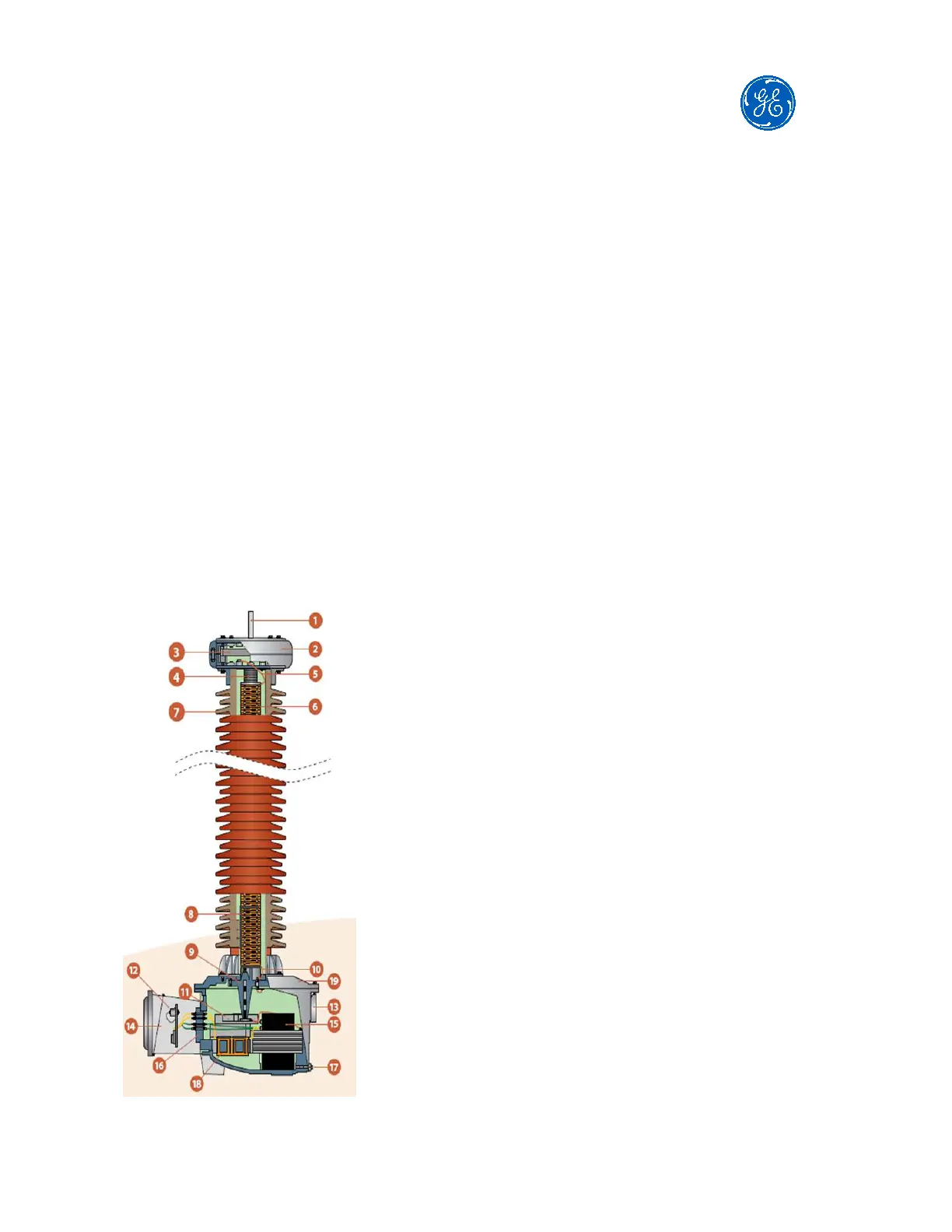
Figure below shows a typical cross-sectional view of an OTCF:
2- Top cover to protect metallic bellows
3- Metallic bellows
4- Compression spring
5- Wire for voltage connection
6- Capacitive elements
7- Insulator: porcelain or composite
8- Voltage divider
9- Bushing
10- Voltage divider LV connection
11- Ferroresonance suppression device
12- Secondary terminals
13- EMU oil level indicator
14- Secondary box
15- Intermediate transformer
16- Oil / air block
17- Oil sample plug
18- Compensation reactor
19- EMU top cover