Instruction Manual
© GE Grid Solutions
5.10. Line trap assembly
If the CVT is used to support a line
trap, refers to the dimensional
drawing for more details.
An adapter plate to fix line trap must
be specified according to the
application.
Verify dimensional drawing to ensure
that the mechanical load imposed by
the line trap, including the forces due
to short circuit and wind, will not
exceed the values used at design
stage.
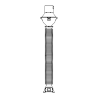
6. OIL LEVEL INDICATOR
For capacitive modules or CD, when required,
oil level indicators are provided. These
indicators are manometer type.
Figure below represents the operating
positions of the indicator. If the indicator
(pointer) is in the green range the CVT can
remain, or enter, in operation. If the
indicator (pointer) is in both red ranges, it is
an incorrect operation condition for the CVT
and it must be removed from operation and
GE must be informed immediately.
Oil level indicator – type manometer
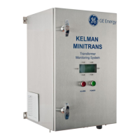
For EMU it is standard to provide an oil level
indicator. It is located on the back of the tank
(opposite side of the secondary terminal
box).