Instruction Manual
© GE Grid Solutions
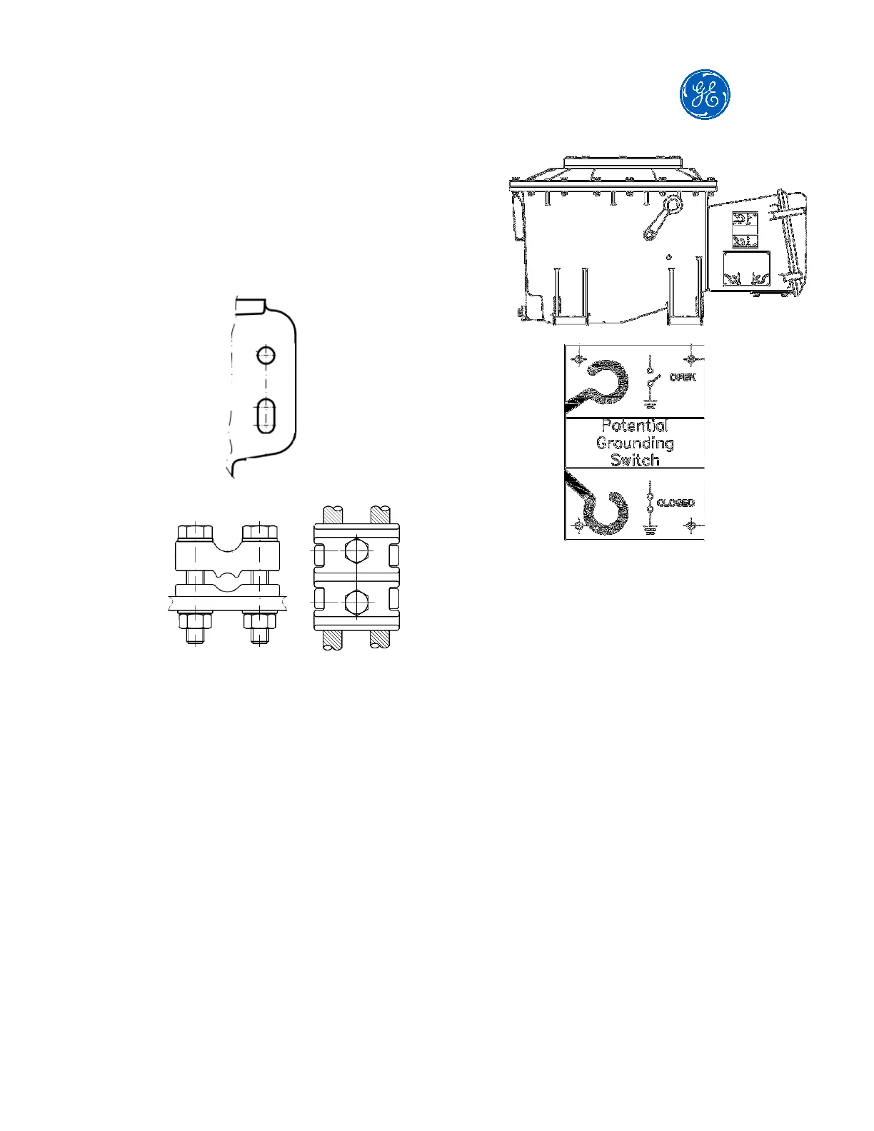
When required, earthing connectors
are provided (check set of drawings to
see the type of the connector and the
range of cables it can receive).
Tightening torque of 5.4 kgf.m on
screw M12.
Example of earthing terminal
Examples of earthing connectors
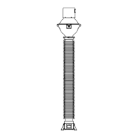
5.8. EMU potential grounding switch
When required, a potential grounding
switch is supplied with the CVT. It is
located on the side of the tank.
Figure below shows the position of
the potential grounding switch of the
EMU
.
The operation time with the potential
grounding switch must be kept to a
minimum, since in this condition the
CD is subjected to a higher dielectric
stress by eliminating the insulation of
the capacitance C2.
It is not recommended to remain with
the potential grounding switch closed
with the CVT energized for a long time
(more than 6 hours).
5.9. Carrier grounding switch
If the carrier system is not connected
to the HF terminal while the CVT is
energized, the carrier grounding
switch located on the side of the
secondary terminal box should remain
in the "Closed" position as shown in
the figure below.