Instruction Manual
© GE Grid Solutions
If the carrier system is not connected
to the HF terminal during operation,
the carrier grounding switch must
remain at the "Closed" position. See
item 5.9.
5.5. Terminal marking
The marking of the primary and
secondary terminals is done according
to the specified standard for the
project. Check the markings on the
set of approved drawings.
The wiring diagram for the secondary
terminals are those shown on the
drawings.
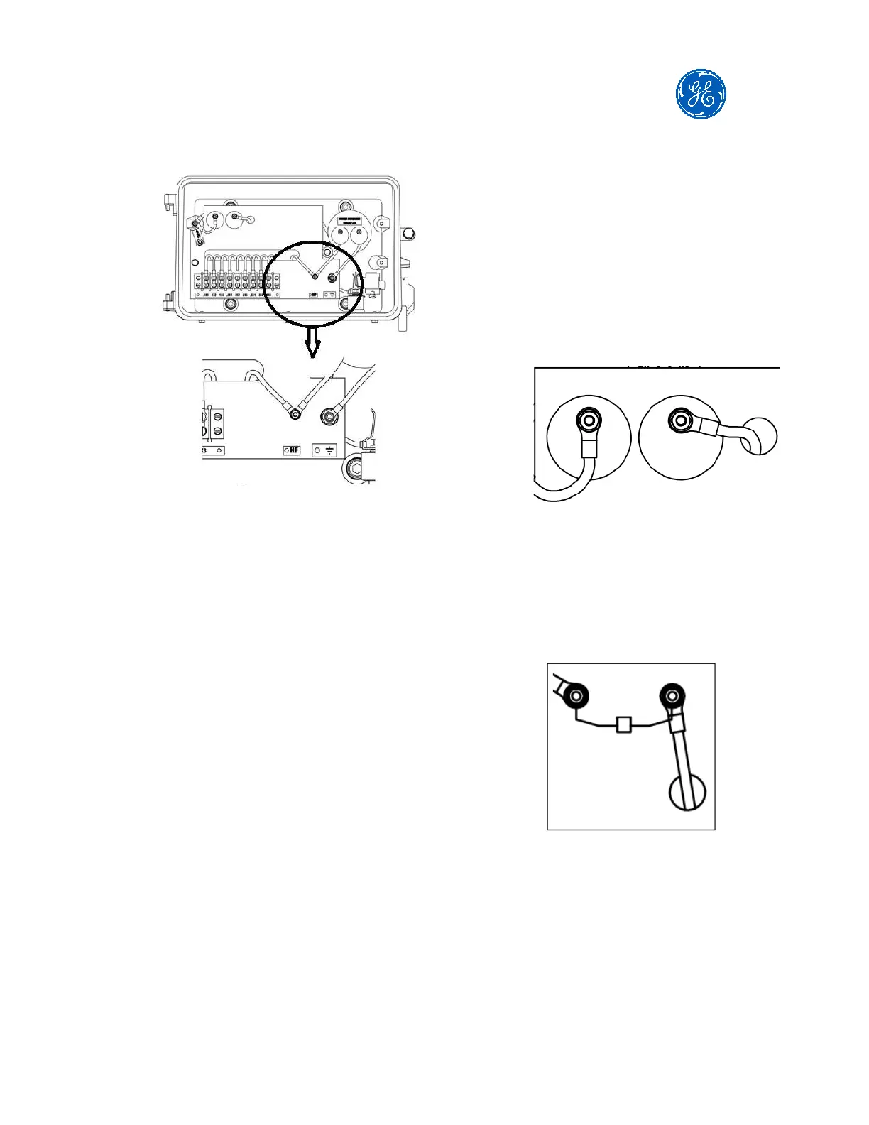
5.6. Protection of compensation reactor
and drain coil
To provide protection against
overvoltages arising from voltage
fluctuations in the CVT, protection
sparkers are supplied to the
compensation reactor and the drain
coil and are located in the secondary
terminal box.
These sparkers may be of two types:
Spark gap: Air insulation with
preset factory setting. Refer to
the CVT secondary terminal box
drawing for more details.
This setting cannot be modified
on-site.
Spark gap type example
Encapsulated: Gas insulation
with pre-set operating voltage.
Refer to the CVT secondary
terminal box drawing for more
details on which type is used.
Encapsulated type example
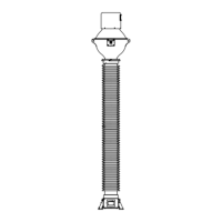
5.7. CVT grounding
The CVT tank has two grounding
points located on the tank's own
body. At least one of the points must
be connected to the substation
earthing system using appropriate
cables.