Appendix B - Settings and Signals
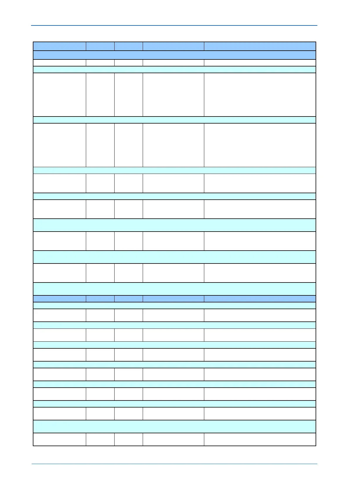
MENU TEXT COL ROW DEFAULT SETTING AVAILABLE OPTIONS
DESCRIPTION
Allows user to change password level 2. (8 characters)
Password Level 3 00 D4 AAAA
4 registers for writing 8 character password
Each register contains a pair of characters
Each register is formatted as follows:-
first character of a pair
second character of a pair
Each character is in the Courier range 33 - 122
Allows user to change password level 3. (8 characters)
Security Feature 00 DF 1
4 registers for writing 8 character password
Each register contains a pair of characters
Each register is formatted as follows:-
first character of a pair
second character of a pair
Each character is in the Courier range 33 - 122
Displays the level of cyber security implemented, 1 = phase 1.
Password 00 E1
4 registers for writing encrypted password
Registers can contain any bit pattern.
Encrypted password entry cell. Not visible via UI
Password Level 1 00 E2
4 registers for writing encrypted password
Registers can contain any bit pattern.
Allows user to change Encrypted password level 1. (8 characters)
Not visible via UI
Password Level 2 00 E3
4 registers for writing encrypted password
Registers can contain any bit pattern.
Allows user to change Encrypted password level 2. (8 characters)
Not visible via UI
Password Level 3 00 E4
4 registers for writing encrypted password
Registers can contain any bit pattern.
Allows user to change Encrypted password level 3. (8 characters)
Not visible via UI
This column contains record configuration
Select Event 01 01 0
From 0 to 1023 in steps of 1
[Unsigned Integer (16 bits)]
This selects the required event record. A value of 0 corresponds to the latest event and so on.
Menu Cell Ref 01 02 (From Record)
Menu Cell Ref
[Cell Reference]
Indicates the type of event
Time & Date 01 03 (From Record)
Time & Date
[IEC870 Time & Date]
Time & Date Stamp for the event given by the internal Real Time Clock.
Event Text 01 04
[ASCII Text (32)]
Up to 32 Character description of the Event (refer to following sections).
Event Value 01 05
Event Value
[Binary Flag (32)/UINT32]
Up to 32 Bit Binary Flag or integer representative of the Event (refer to following sections).
Select Fault 01 06 0
From 0 to 14 in steps of 1
[Unsigned Integer (16 bits)]
Setting range from 0 to 14. This selects the required fault record from the possible 15 that may be stored. A value of 0 corresponds to the
latest fault and so on.
Faulted Phase 01 07
 Loading...


