P54A/B/C/E Appendix C – Wiring Diagrams
P54xMED-TM-EN-1 C1
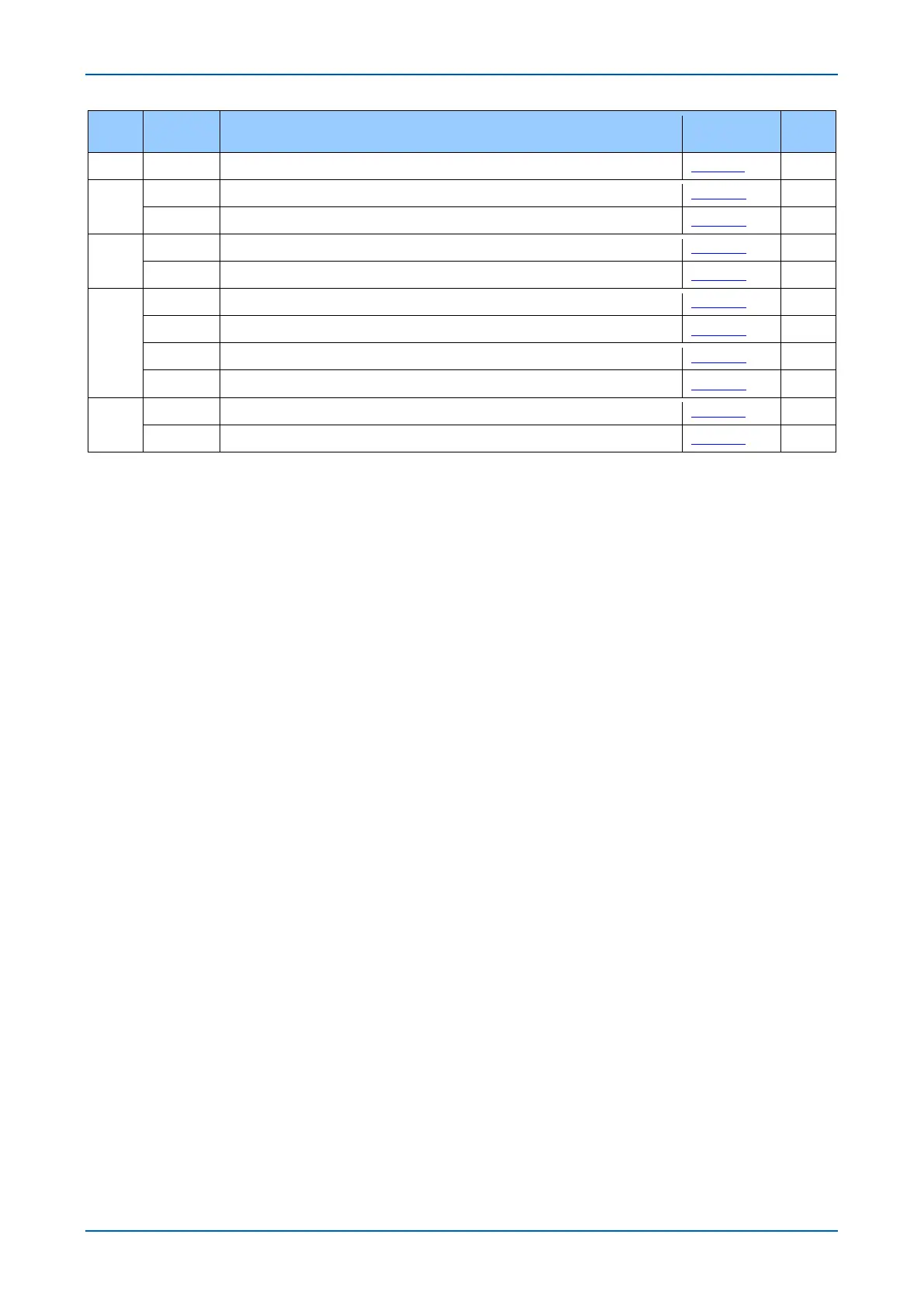
MODEL
OPTION*
EXTERNAL CONNECTION DIAGRAM TITLE
SHEET
ISSUE
Px4x - COMMS OPTIONS MICOM Px40 PLATFORM 10Px4001-1 J
P54A
A to R CURRENT DIFF 1 RELAY 8 INPUTS, 8 OUTPUTS & SEF (40TE) 10P54A01-1 B
A to R CURRENT DIFF 1 RELAY 8 INPUTS, 8 OUTPUTS & SEF (40TE) 10P54A01-2 B
P54B
A to R CURRENT DIFF 2 RELAY 8 INPUTS, 8 OUTPUTS & SEF (40TE) 10P54B01-1 B
A to R CURRENT DIFF 2 RELAY 8 INPUTS, 8 OUTPUTS & SEF (40TE) 10P54B01-2 B
P54C
A to R CURRENT DIFF 2 RELAY 16 INPUTS, 8 OUTPUTS & SEF (60TE) 10P54C01-1 B
A to R CURRENT DIFF 2 RELAY 16 INPUTS, 8 OUTPUTS & SEF (60TE) 10P54C01-2 B
S to Z, 0 to 5 CURRENT DIFF 3 RELAY 16 INPUTS, 12 OUTPUTS (4 HIGH BREAK) & SEF (60TE) 10P54C02-1 B
S to Z, 0 to 5 CURRENT DIFF 3 RELAY 16 INPUTS, 12 OUTPUTS (4 HIGH BREAK) & SEF (60TE) 10P54C02-2 B
P54E
S to Z, 0 to 5 CURRENT DIFF RELAY 1 OR 3 POLE AUTORECLOSE & CHECK SYNCH (80TE) 10P54E01-1 B
S to Z, 0 to 5 CURRENT DIFF RELAY 1 OR 3 POLE AUTORECLOSE & CHECK SYNCH (80TE) 10P54E01-2 B
* When selecting the applicable wiring diagram(s), refer to appropriate model’s CORTEC.