Do you have a question about the GE PCVH480EKWW Series and is the answer not in the manual?
Information intended for experienced individuals; repair attempts may cause injury or damage.
To avoid personal injury, disconnect power before servicing the product.
Ensure grounding wires, screws, and clips are properly fastened after service.
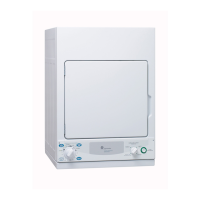
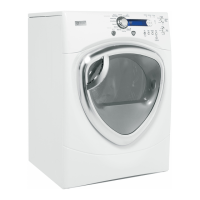
Identifies the location of the model and serial number on the dryer.
The mini manual is located behind the control panel.
Explains the function of Time, Temp, and Sensor buttons for cycle adjustments.
Procedure to lock and unlock the control panel using the TEMP and SENSOR pads.
Causes the dryer to beep when clothes reach a damp level; continues cycle.
Details the optional stacking kit (GE kit # GE24STACK) and required tools for installation.
Step-by-step guide to installing the stack bracket kit, including removing leveling legs and adding rubber pads.
Instructions for installing the bracket to the washer and then the dryer onto the washer.
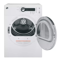
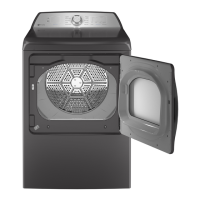
Illustrates the lint screen and states that it opens for cleaning.
Details a clip for assembly and mentions testing the door switch via 'Test Mode'.
Shows the drum lamp assembly after front panel removal and how it's secured.
Provides voltage details for the LED lighting and notes PCB timeout after 15 minutes.
Instructions for removing the top panel by unscrewing two rear hex head Phillips screws.
How to remove two screws and lift/pull the control panel forward to disengage it.
Shows the PCB assembly after control panel removal.
Instructions on pulling the control knob off the PCB shaft and noting its D-shaft alignment.
Details removing four Phillips screws and pressing locking tabs to release the PCB.
Indicates that rubber and plastic push buttons are available as separate parts.
Steps to remove the front panel, including unscrewing and pulling it out.
Instructions to remove four screws and disconnect sensor/lamp harnesses.
Details sliding the bottom out and dropping to release the upper support tab.
Explains that drum rollers are mounted to the front drum support and how to remove them.
Steps to remove the filter inlet assembly, disconnect sensor wiring, and test the sensor.
Instructions to remove two front screws and lift the assembly out of the drum support.
Steps to remove the rear cover for access to the belt and idler.
How to push the idler to release belt tension and remove the belt from the motor pulley.
Instructions for sliding the drum assembly forward to remove it from the cabinet.
Discusses replacing the drum assembly if the shaft is damaged and the washer bearing as a replaceable part.
Labels the felt gasket assembly, felt gasket bracket, and rear drum bearing assembly.
Instructions to remove three Phillips screws from the felt gasket bracket and note the UP ARROW.
Note the up arrow for reinstallation; gasket attached with push-through dart tabs.
Describes the belt switch securing, its normally closed state, and how a broken belt opens it.
Details the idler assembly attachment to the motor bracket with a shoulder screw and spring.
Steps to remove blower housing screws, hold pulley with wrench, and remove the 14mm nut.
States they are inside the blower housing and removed with a single Phillips head screw.
Instructions to disconnect motor harness, remove front/rear motor clamps, and blower wheel.
Details wiring colors for centrifugal switch and notes testing resistance.
Instructions to remove the rear cover to access and remove the heater assembly.
Describes dual elements, replacement as an assembly, and non-replaceable thermostats.
Provides K OHMS to °F conversion for thermistors and OPEN/CLOSE temperatures for thermostats.
Identifies key connectors (CN4, CN2, CN1) and relays (RY1, RY6) on the PCB.
Locates DC outputs, thermistor, touch sensor, drum lamp pins, and explains door check function.
Details testing motor windings resistance (approx. 1.7 ohms) and identifying open circuits.
Describes testing heater resistance (approx. 130 ohms) and Hi-Limit thermostat (0 ohms if closed).
Instructions to enter service mode from idle state by pressing Signal, Extended Tumble, Signal, Extended Tumble.
't01' will appear in the display upon successful entry into service test mode.
Explains using the rotary knob for tests, START/PAUSE to initiate, and POWER to return or exit.
Lists various test modes including software version, error codes, UI test, door switch, motor, thermistor, and moisture sensor.
Details error codes (E00, tS, t0, dE, od, HE, FE, bE2, 3E1, 3E2) and corrective actions.
Presents the electrical schematic for the dryer's electronic control system.
| Brand | GE |
|---|---|
| Model | PCVH480EKWW |
| Type | Electric Dryer |
| Color | White |
| Voltage | 240V |
| Amperage | 30A |
| Drum Material | Aluminized Alloy |
| Control Type | Electronic |
| Number of Cycles | 12 |
| Number of Temperature Settings | 4 |
| Wrinkle Prevention Option | Yes |
| Moisture Sensor | Yes |
| End of Cycle Signal | Yes |
| Energy Star Certified | No |
| Width | 27 in. |
| Weight | 130 lbs |